
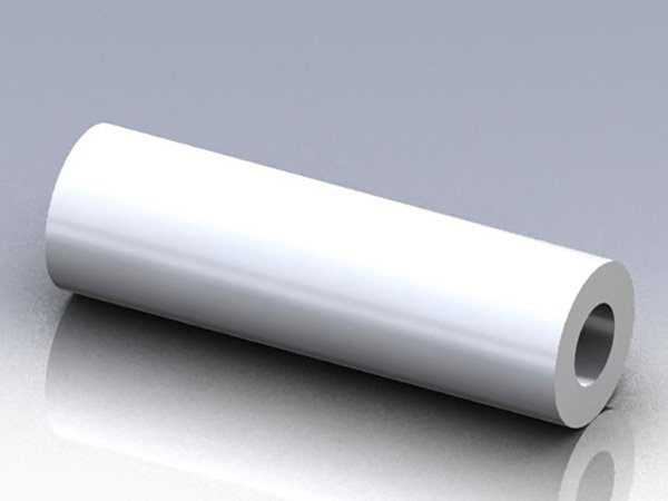
PS-P01 / Existing bicycle reference
Pivot Shaft
Existing technical illustration from the original product record. Geometry reference only; no fit or material is inferred for a new project.
View the Original Part RecordPrecision Pivot & Shaft Components
Define the working interfaces, shoulders, bores and threads for a project-specific manufacturing review.
The assembly defines which shaft surfaces locate, support or retain the adjoining parts. Include the functional interfaces and the relationship between shoulders, bores, threads and other features so the review covers the complete part.
Existing bicycle axle-core records remain a specialist reference within this family. They retain their original identities, drawings and detail links. They are not automatically qualified for a new vehicle, mechanism or loading condition.
Six existing technical illustrations show different axle-core forms. Their source records remain the authoritative reference.
Existing technical illustration from the original product record. Geometry reference only; no fit or material is inferred for a new project.
View the Original Part Record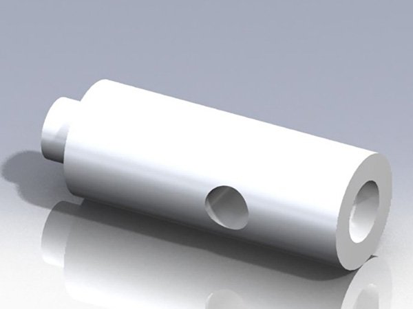
Existing technical illustration from the original product record. Geometry reference only; no fit or material is inferred for a new project.
View the Original Part Record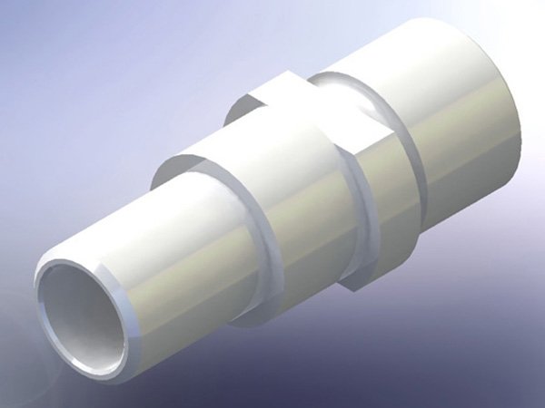
Existing technical illustration from the original product record. Geometry reference only; no fit or material is inferred for a new project.
View the Original Part Record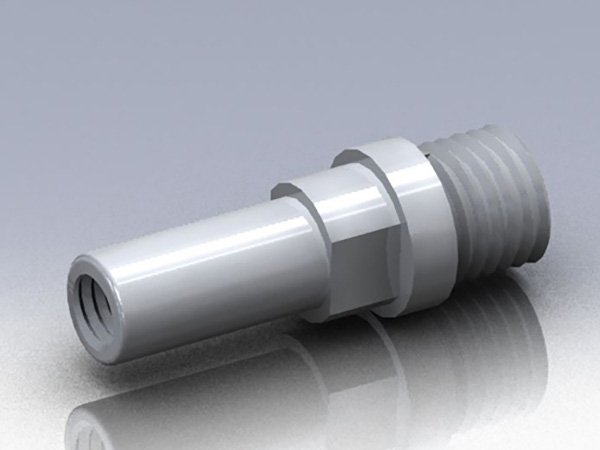
Existing technical illustration from the original product record. Geometry reference only; no fit or material is inferred for a new project.
View the Original Part Record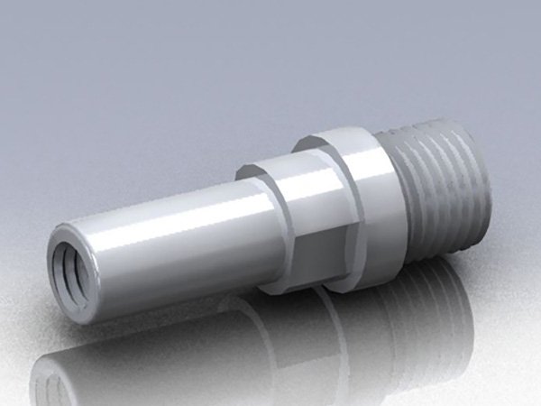
Existing technical illustration from the original product record. Geometry reference only; no fit or material is inferred for a new project.
View the Original Part Record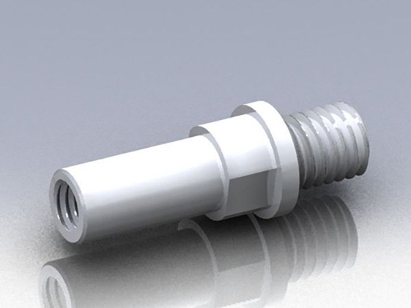
Existing technical illustration from the original product record. Geometry reference only; no fit or material is inferred for a new project.
View the Original Part RecordDescribe what each feature must do in the assembly, not only what it looks like in a rendering.
Stepped, threaded, pivot and hollow forms may involve different access, material and inspection questions. A cross-hole, flat or groove needs its position relative to the working shaft surfaces defined on the drawing.
Generic terminology does not establish an eccentric-shaft, high-speed, precision-ground or gear-shaft capability. Those specialized routes require their own evidence and project review.
Identify the surfaces used to locate and inspect the part. State relationships between shoulders, holes and other functional features.
Include bearing, housing, linkage or retaining-part requirements where they determine the interface. Avoid assuming a universal fit.
Define bore depth, wall geometry, access and finished acceptance requirements rather than inferring them from an external image.
State the required dimensions, geometric controls, surface state and documentation. Acceptance values follow the agreed drawing.
A reference shaft is not evidence for an unlimited size, speed or material range.
Submit the full length, diameters, material condition and combined features for review. The website does not assign an unverified maximum diameter, universal length ratio or tolerance to this family.
Large transmission shafts, high-speed spindles, long guide shafts, hardened precision-ground forms and gear shafts need separate capability confirmation. The presence of a turned surface or a bicycle axle example does not prove those routes are available.
Use the established series and engineering resource without changing their technical identity.
The PS-P axle-core series and pivot-bolt white paper provide the existing bicycle-specific context. Their original part references, dimensions and download routes remain separate from a new application's production specification.
For another vehicle or mechanism, state its own mating interfaces, operating requirements, validation plan and acceptance criteria. Do not transfer a bicycle drawing or catalog statement as proof of suitability.
Send the geometry and acceptance inputs that control your assembly.
For a shaft or pin family, use separate references and revisions for each geometry. Identify the mating components, material and finish, the sample or batch quantity, and any inspection or customer approval requirements.
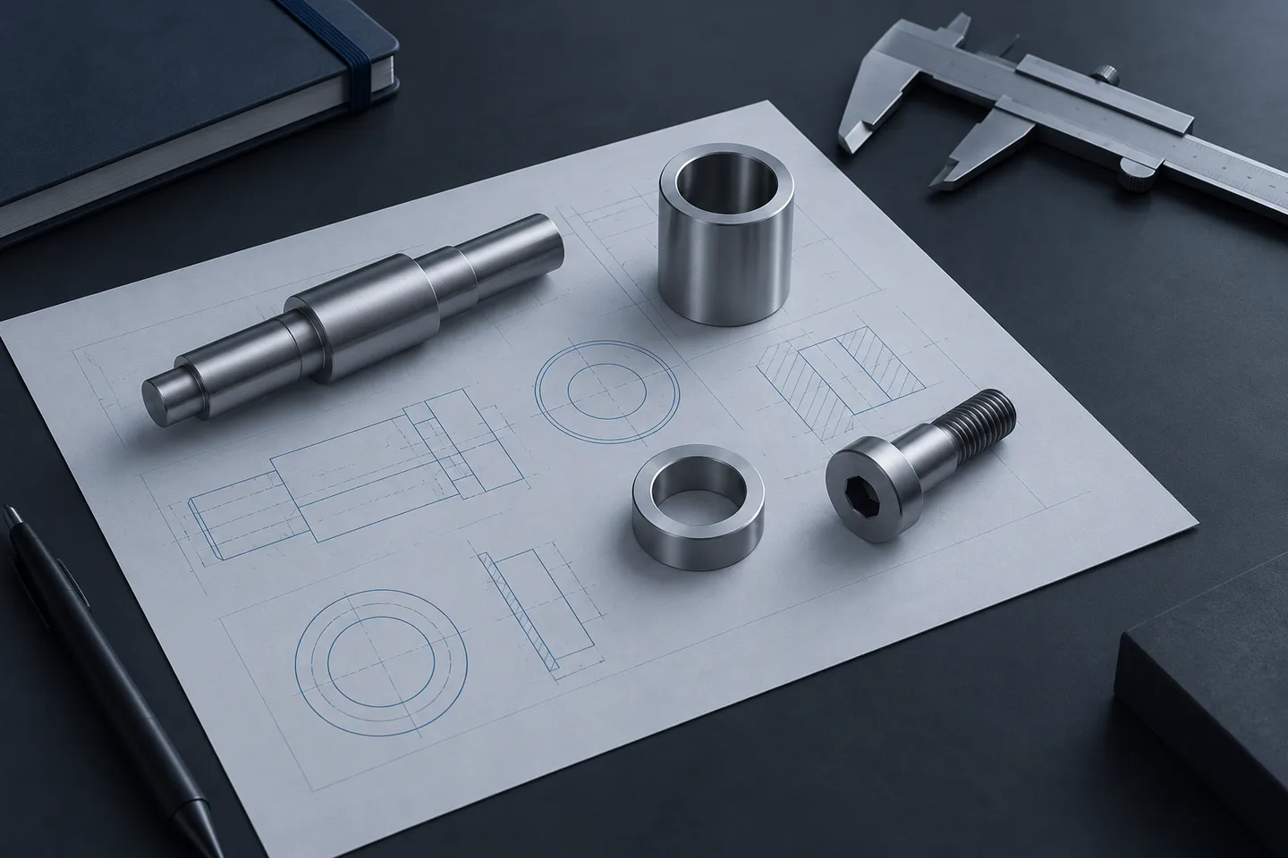
Clarify the drawing before assuming a manufacturing route.
Provide all required features and their position requirements in the drawing. The route is reviewed against the complete geometry rather than one feature alone, with any secondary operation confirmed in the project scope.
No single tolerance is appropriate for every project. Dimensional, geometric and surface requirements should be specified on the drawing and confirmed during manufacturing review.
An existing example does not establish suitability for another assembly. The new application, mating interfaces, operating requirements and acceptance plan need their own review.
No. An interface describes the part requirement, not the process used to achieve it. Any grinding, hardening or specialized route must be confirmed separately rather than inferred from a category name.
Continue by component geometry, process or application.