
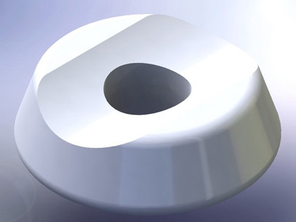
PS-H02 / Existing bicycle reference
Spacer Washer
Existing technical illustration from the original product record. Geometry reference only; no fit or material is inferred for a new project.
View the Original Part RecordDrawing-Defined Component Families
Review sleeves, bushings, spacers and flanged forms around the fit, geometry and acceptance requirements in your drawing.

A sleeve, bushing or spacer is defined by more than its outer shape. The bore, end faces, material condition and position within the assembly determine how the part locates, separates or interfaces with adjacent components.
This family organizes non-shaft turned forms without replacing the original product records. Sleeves, bushings, flanged parts and threaded forms can be discussed through your drawing; their production scope is confirmed individually rather than inferred from the category name.
These four original bicycle references provide geometry context. They do not establish experience with every turned-component form.
Existing technical illustration from the original product record. Geometry reference only; no fit or material is inferred for a new project.
View the Original Part RecordExisting technical illustration from the original product record. Geometry reference only; no fit or material is inferred for a new project.
View the Original Part Record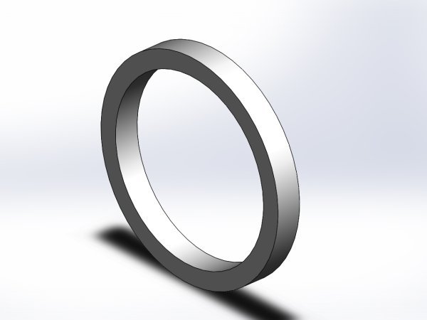
Existing technical illustration from the original product record. Geometry reference only; no fit or material is inferred for a new project.
View the Original Part Record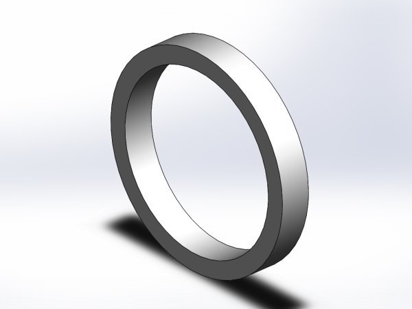
Existing technical illustration from the original product record. Geometry reference only; no fit or material is inferred for a new project.
View the Original Part RecordExplain which surfaces control the assembly before specifying how the part should be manufactured.
Mark the features that locate the part and the surfaces that contact adjacent components. A drawing should distinguish a general clearance hole from an interface with a specific fit or acceptance requirement.
Include flats, holes, slots, grooves and threads when needed. Their presence raises a process-review question; it does not establish that the part is made on a mill-turn machine or completed in one setup.
Identify the mating shaft or housing, the datum relationship and any surface requirement that controls assembly.
State which faces set the assembled distance and whether the acceptance condition applies before or after treatment.
Define feature location, thread specification and access requirements. Include edge and burr acceptance where important.
Give the required grade, condition and finishing scope. Do not substitute an appearance description for a material specification.
Dimensional and surface requirements are project inputs, not a single tolerance promised for all parts.
When the component controls clearance, spacing or location, provide mating-part information and the drawing datums. Identify which dimensions are critical to acceptance and whether they are inspected in the finished condition.
Concentricity, runout, end-face relationships, edge condition and surface requirements should be specified where the assembly needs them. No additional dimensions or tolerance values are inserted into your engineering drawing by a catalog page.
Separate the component requirement from the manufacturing-service question.
Provide the specified material grade and state, requested surface treatment and any customer-defined wear, appearance or corrosion acceptance criteria. These are reviewed with the geometry and quantity; a general material category is not a performance guarantee.
CNC machining is part of the confirmed in-house capability set. Heat treatment, testing and finishing can involve qualified partners within the agreed route. See the dedicated CNC turning page for process inputs and the existing surface-treatment resource for the site's established technical context.
A sample discussion and a production order need a common specification.
Identify the drawing revision, individual part references, quantity and mating interfaces. A sample can help explain missing geometry, but it does not replace agreed production requirements.
Review the complete geometry, material, finish and inspection needs together. The quotation identifies the accepted manufacturing scope and any confirmed partner operations.
Confirm sample requirements, critical dimensions, required reports and packing instructions before production approval. Avoid relying on a general catalog image as the acceptance standard.
Use the agreed part number, revision and specification for later orders. State any engineering changes so a previous quotation is not treated as approval of a changed drawing.
State the functional fit and important surfaces so the first review can focus on your actual assembly.
A sample can explain a turned form when a complete drawing is not yet available. Agree the geometry, material and acceptance requirements before production, and identify any measurement or drawing work as part of the quotation scope.
Practical guidance before an OEM inquiry.
Provide the drawing or reference, material, quantity, finish and important dimensions. Include mating-part information where the component controls clearance, location or spacing, together with any required inspection documents.
Mark the required flats, holes or slots on the drawing. The complete combination is reviewed to identify a suitable, confirmed route. Combined features do not by themselves prove a mill-turn process.
A sample supports an initial discussion. Production requires agreed geometry, material and acceptance requirements. Any measurement or drawing work should be included in the quotation scope.
No. The drawing and acceptance requirements define the dimensional, geometric and surface criteria for the individual part. A product-family label is not a tolerance specification.
Keep the original references and choose the next question by geometry or manufacturing scope.