
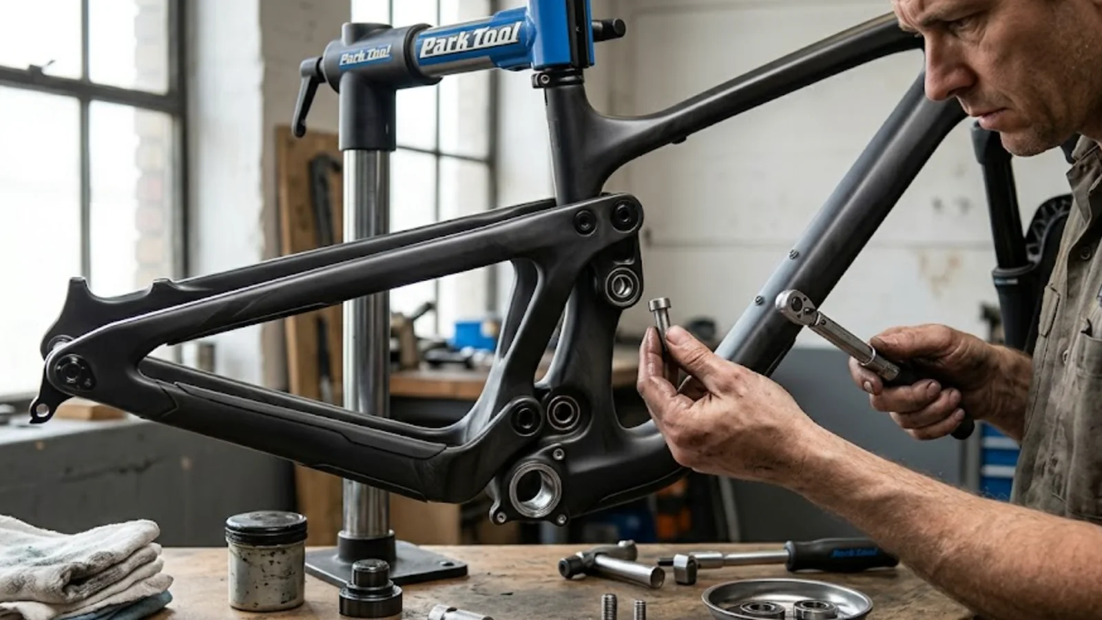
Proper fastener installation is the difference between a reliable, safe bicycle and a warranty claim waiting to happen. This guide provides production-ready procedures for bicycle assembly factories, frame manufacturers, component suppliers, and OEM brands. Every procedure is based on ISO 16047 & VDI 2862 methodology and validated against major brand assembly specifications (Shimano, SRAM, Fox, RockShox, Hope).
Pre-Installation Checklist
Critical verification steps before any fastener is tightened
| # | Check Item | Requirement | Common Non-Conformance |
|---|---|---|---|
| 1 | Fastener Inspection | Check for surface damage, coating integrity, burrs, or contamination. Threads must be clean and free of debris. | Rust spots on plated fasteners; damaged hex drive from previous assembly attempts |
| 2 | Mating Thread Condition | Verify female threads are clean, undamaged, and free of paint/powder coat overspray. Chase threads if necessary. | Powder coat in frame threads; crossed threads from power-tool assembly |
| 3 | Torque Wrench Calibration | Tool calibrated within last 90 days. Verification within ±4% of indicated value per ISO 6789. | Expired calibration; click-type wrench stored at max setting (spring set) |
| 4 | Thread Preparation Material | Confirm correct compound for the application: grease, anti-seize, thread locker, or carbon paste. Check expiry date on thread locker. | Using general grease where Loctite is specified; expired thread locker (shelf life typically 12–24 months) |
| 5 | Fastener Compatibility | Verify bolt length, thread pitch, and head style match the engineering BOM. Confirm property class meets specification. | Substituting 8.8 for 10.9 spec; wrong grip length causing bottom-out or insufficient engagement |
| 6 | Assembly Environment | Ambient temperature 15–30°C. Clean, dry work area. No contamination risk (oil mist, dust, moisture). | Cold workshop below 10°C affecting thread locker cure; outdoor assembly in humid conditions |
Thread Preparation & Chemical Application
Correct lubricant, locking compound, and anti-seize selection by application
| Application | Product Type | Recommended Product | Application Method | Cure / Set Time | Temperature Range |
|---|---|---|---|---|---|
| Thread Lockers (Anaerobic) | |||||
| Small fasteners M3–M6 (rotor bolts, lever clamps, derailleur) | Low Strength (Purple) | Loctite 222 / Permabond A1042 | 1–2 drops on male thread, first 3–4 threads | Fixture: 10–20 min Full cure: 24 h | −55 to +150°C |
| Medium fasteners M6–M12 (brake caliper, shock mount, pivot bolts) | Medium Strength (Blue) | Loctite 243 / Permabond A1046 | 2–3 drops, cover full thread engagement length | Fixture: 10 min Full cure: 3–6 h | −55 to +180°C |
| Permanent assembly (bottom bracket cup, cassette lockring) | High Strength (Red) | Loctite 263 / Permabond A1056 | Apply to clean, dry threads. Do not over-apply. | Fixture: 10 min Full cure: 24 h | −55 to +150°C |
| Post-assembly wicking (pre-assembled adjusters) | Wicking Grade (Green) | Loctite 290 | Apply to assembled joint; wicks into threads by capillary action | Fixture: 5 min Full cure: 24 h | −55 to +150°C |
| Anti-Seize Compounds | |||||
| Titanium → Titanium, Ti → Aluminum | Copper-Free Anti-Seize | Loctite LB 8023 / Ti-Prep | Thin coat on male threads only. Do not apply to bearing surface. | N/A (non-curing) | −30 to +1100°C |
| Steel → Aluminum (general assembly) | Standard Anti-Seize | Loctite LB 8009 / Permatex 81343 | Light coat, avoid excess that could contaminate bearings | N/A | −30 to +870°C |
| Stainless → Stainless, Exhaust mounts | Copper Anti-Seize | Loctite C5-A / Permatex 31163 | Apply to threads only. High-temp rated for brake/exhaust zones. | N/A | −30 to +980°C |
| Assembly Pastes & Greases | |||||
| Carbon fiber clamping (stem, seatpost, handlebar) | Carbon Assembly Paste | Finish Line Fiber Grip / Muc-Off Carbon Gripper | Apply thin even layer to clamping surface (not threads) | N/A | −20 to +120°C |
| General thread lubrication (steel fasteners) | Assembly Grease | Park Tool PPL-1 / Shimano Premium Grease | Light coat on threads and under-head bearing surface | N/A | −20 to +120°C |
| Bottom bracket & pedal threads | Heavy-Duty Grease | Park Tool HPG-1 / Motorex Bike Grease 2000 | Generous coat on shell and cup threads; prevents seizing | N/A | −30 to +150°C |
Tightening Procedures & Patterns
Sequential tightening methodology for uniform clamp load distribution
Multi-Bolt Pattern Tightening
| Pattern | Application | Passes | Increments |
|---|---|---|---|
| Cross-Pattern (Star) | Stem faceplate (4-bolt), rotor (6-bolt), chainring (4–5 bolt) | 2–3 passes | Pass 1: 50% → Pass 2: 80% → Pass 3: 100% target torque |
| Spiral Pattern | Brake caliper post mount, engine case covers | 2 passes | Pass 1: 60% → Pass 2: 100% target torque |
| Alternating Side | Pinch bolts (crank arm, seatpost clamp) | 3–4 passes | Alternate left/right in small increments; equal gap both sides |
| Center-Outward | Cylinder head, suspension linkage plates | 3 passes | Pass 1: 40% → Pass 2: 70% → Pass 3: 100% target torque |
Torque Application Method
| Method | Accuracy | Best For |
|---|---|---|
| Torque Wrench (Click-Type) | ±4% | All safety-critical joints. Factory-preferred method. |
| Torque Wrench (Digital/Electronic) | ±2% | QC audit, process validation, high-value assemblies |
| Angle-Controlled Tightening | ±1.5% preload | Cylinder head bolts, suspension pivot axles |
| DC Tooling (Production Line) | ±3% | High-volume assembly with traceability |
| Hand Tight + Angle | ±15% | Bottom bracket cups, pedal installation |
Material-Specific Installation Techniques
Critical differences when installing into aluminum, carbon fiber, steel, and titanium
| Substrate | Key Risk | Procedure | Thread Prep | Re-Torque Required |
|---|---|---|---|---|
| Aluminum Frame / Component | Thread stripping, galvanic corrosion with steel fasteners | 1. Chase threads to remove paint/powder coat 2. Apply anti-seize or grease to bolt threads 3. Reduce torque 25–30% from dry steel values 4. Never use impact tools — hand tools only 5. Verify thread engagement ≥ 1.5× bolt diameter |
Anti-seize (steel bolts) Grease (aluminum bolts) |
After 100–200 km for structural joints |
| Carbon Fiber Frame / Component | Delamination, crush failure, invisible damage from over-torque | 1. Apply carbon assembly paste to clamping surfaces (not threads) 2. Use torque wrench with ±4% accuracy minimum 3. Reduce torque 35–50% from aluminum values 4. Verify even clamp gap (top/bottom equal) 5. Never exceed manufacturer maximum torque marking 6. Use anti-crush sleeve inserts where specified |
Carbon paste on clamping surface only |
Yes — after first 50 km ride. Carbon paste settles. |
| Steel Frame / Component | Galling on high-strength fasteners, hydrogen embrittlement | 1. Verify thread condition — no rust, debris, or damage 2. Apply light oil or assembly grease to threads 3. Use full dry torque values 4. For 10.9/12.9: verify coating is hydrogen-embrittlement resistant 5. Never install high-strength fasteners wet (moisture + torque = hydrogen risk) |
Light oil or assembly grease | After 50–100 km for safety-critical (brakes) |
| Titanium Component / Fastener | Severe galling, galvanic corrosion with carbon, relaxation | 1. Copper-free anti-seize is MANDATORY on all Ti threads 2. Reduce installation speed — no power tools 3. Reduce torque 20–25% from steel values 4. Use Ti-prep or dedicated titanium anti-seize 5. Titanium bolt into carbon: use isolating washer 6. Never use standard grease — insufficient galling protection |
Ti-specific anti-seize (copper-free) mandatory |
Yes — every 50 hours riding. Ti relaxes more than steel. |
Carbon Fiber: Critical Rules
- Carbon does NOT yield — it fractures. No warning before failure.
- Carbon assembly paste contains micro-spheres that increase friction, enabling lower clamp torque while preventing slip.
- Never use standard grease on carbon clamping surfaces — it reduces friction and requires higher clamp force to prevent slip.
- The manufacturer-printed torque value on the component is the absolute maximum. Install 10–15% below if using assembly paste.
- Check for even gap between clamp halves. Uneven gap indicates misalignment or over-torque on one side.
- Inspect for hairline cracks around bolt holes using magnifying loupe after first 50 km. Replace component if any crack detected.
- Use anti-crush sleeves (internal metal bushings) in all carbon clamping zones to distribute load.
Aluminum Frame: Best Practices
- The aluminum thread is the weak point — the bolt will always win.
- Every aluminum threaded hole on a frame should be chased (cleaned) with a thread chaser before assembly — powder coat and paint routinely contaminate frame threads.
- Minimum thread engagement: 1.5× diameter for coarse, 2.0× diameter for fine.
- Use threaded inserts (helicoil, time-sert) for any structural joint that will be disassembled more than 10 times in the product lifetime.
- Brake mount bosses (post mount): helicoil or steel insert is strongly recommended for production frames. Aluminum threads in M6 brake mounts will strip at ~15 Nm.
- Bottom bracket shells must be faced and chased before cup installation. Misaligned threads cause bearing misalignment and premature wear.
- Anti-seize on all steel-into-aluminum joints. This prevents galvanic corrosion that can permanently seize bolts.
Production Line Work Instructions
Standardized assembly procedures for factory environments
| Station | Assembly Zone | Tool Required | Thread Prep | Torque (Nm) | Pattern | QC Check |
|---|---|---|---|---|---|---|
| Station 1: Frame Preparation | ||||||
| 1.1 | Bottom bracket shell chase & face | BB tap + facing tool | Cutting oil | — | — | Verify face parallel ±0.05 mm |
| 1.2 | Brake mount thread chase (M6×1.0) | M6×1.0 thread chaser | Dry | — | — | Bolt threads in smoothly by hand |
| 1.3 | All threaded eyelets (rack, fender, bottle) | M5×0.8 thread chaser | Dry | — | — | Visual: no paint in threads |
| Station 2: Bottom Bracket & Crankset | ||||||
| 2.1 | BB cup installation (BSA threaded) | BB tool + torque wrench | Heavy grease on shell threads | 35–50 | Drive side first (LH thread!) | Verify fully seated; no gap |
| 2.2 | Crank arm installation (Hollowtech-type) | 5 mm hex + torque wrench | Grease pinch bolt threads | 12–14 | Alternate left/right pinch bolts | Verify preload; no lateral play |
| 2.3 | Chainring bolts (4-arm / 5-arm) | T30 Torx or 5 mm hex | Grease threads | 8–12 | Cross-pattern, 2 passes | All bolts at uniform torque |
| Station 3: Cockpit (Stem & Handlebar) | ||||||
| 3.1 | Stem steerer clamp bolts | 4 mm / 5 mm hex + torque wrench | Carbon paste on steerer (if carbon) | 5–10 (see stem marking) | Alternate top/bottom bolts | Headset preload verified first |
| 3.2 | Stem faceplate bolts | 4 mm hex + torque wrench | Carbon paste on bar surface | 4–6 | Cross-pattern, 2 passes, equal gap | Verify 1–2 mm gap top and bottom |
| 3.3 | Brake lever + shift lever clamps | 3 mm / 4 mm hex | Carbon paste (carbon bar) | 4–6 | Single bolt | Lever rotates under firm pressure |
| Station 4: Brakes | ||||||
| 4.1 | Caliper mount bolts (post mount) | 5 mm hex + torque wrench | Loctite 243 (2 drops) | 8–10 | Spiral pattern (2 passes) | Line inspector: re-torque check |
| 4.2 | Rotor bolts (6-bolt) | T25 Torx + torque wrench | Loctite 243 pre-applied | 5–6 | Cross-pattern, 2 passes | All bolts verified tight |
| Station 5: Drivetrain | ||||||
| 5.1 | Rear derailleur hanger bolt | 5 mm hex + torque wrench | Grease threads | 8–10 | Single bolt | Verify hanger alignment |
| 5.2 | Cassette lockring | Cassette tool + torque wrench | Light grease on threads | 40 | Single | No play in cassette cogs |
| Station 6: Seatpost & Saddle | ||||||
| 6.1 | Seatpost clamp bolt | 4 mm / 5 mm hex | Carbon paste (carbon post/frame) | 4–6 | Single bolt | Post does not slip under body weight |
| 6.2 | Saddle rail clamp bolts | 5 mm / 6 mm hex | Light grease on threads | 10–15 | Alternate front/rear bolts | Saddle angle and position verified |
| Station 7: Wheels | ||||||
| 7.1 | Thru-axle installation | 6 mm / 8 mm hex | Light grease on threads | 10–15 | Single | Wheel spins freely; no brake rub |
| 7.2 | Tubeless valve stem nut | Hand / valve core tool | Dry | 1.5–2.5 | Single | Snug only — do not crush O-ring |
| Station 8: Final QC | ||||||
| 8.1 | Safety-critical bolt audit torque check | Digital torque wrench | N/A | Verify ≥ target | Sample: every Nth unit | Document on QC traveler |
| 8.2 | Torque stripe marking (paint marker) | Paint marker (contrasting color) | N/A | N/A | Mark all safety bolts | Visual confirmation completed |
Common Installation Errors & Root Causes
The most frequent assembly defects and how to prevent them in production
| # | Defect | Root Cause | Consequence | Prevention |
|---|---|---|---|---|
| 1 | Stripped aluminum threads | Over-torque; power tool without torque control; paint in threads | Component scrap; frame warranty claim; safety hazard | Thread chase before assembly; calibrated torque wrench; helicoil for structural joints |
| 2 | Carbon component crush | Over-torque; no carbon paste; uneven clamp gap | Catastrophic carbon failure during ride; liability claim | Carbon paste; torque wrench ±4% accuracy; even gap verification gauge |
| 3 | Seized/stuck bolts | No anti-seize on steel-into-aluminum; stainless-on-stainless galling | Unable to service; destructive extraction required; component damage | Anti-seize compound on all steel-into-aluminum and Ti joints; thread preparation SOP |
| 4 | Loose bolts after ride | No thread locker on vibration-critical joints; insufficient preload; relaxation | Brake caliper loosening; rotor bolt failure; handlebar slip | Loctite 243 on all safety bolts; re-torque after break-in period; cross-pattern tightening |
| 5 | Thread locker failure | Applied to greasy/oily threads; expired product; insufficient cure time before loading | Thread locker does not cure; bolt loosens in service | Clean threads with IPA before application; check expiry date; allow full cure before packaging |
| 6 | Inconsistent clamp gap | Uneven tightening sequence; faceplate misalignment; bolt length mismatch | Uneven clamping force; carbon stress concentration; slip under load | Cross-pattern tightening; gap gauge; verify bolt length from BOM; feeler gauge check |
| 7 | Bottom bracket creak | Shell not faced/chased; insufficient grease; cup not fully seated | Creaking noise; bearing misalignment; premature BB bearing failure | Face and chase every frame; generous grease application; verify full seating with feeler gauge |
| 8 | Hydrogen embrittlement cracking | High-strength fasteners (10.9/12.9) with electroplated zinc coating exposed to moisture during tightening | Delayed brittle fracture; sudden bolt failure without warning | Specify Dacromet or Zn-Ni coating for 10.9+; never install wet; verify coating certs from supplier |
Recommended Tooling & QC Equipment
Production-grade tools for professional bicycle assembly
| Equipment | Specification | Application | Calibration Interval |
|---|---|---|---|
| Click-Type Torque Wrench 2–10 Nm | ±4% accuracy, 1/4" drive, ISO 6789 Class 2 | Cockpit, brake levers, rotor bolts, saddle clamps | Every 5,000 cycles or 12 months |
| Click-Type Torque Wrench 10–60 Nm | ±4% accuracy, 3/8" drive, ISO 6789 Class 2 | Brake calipers, crank bolts, suspension pivots, BB cups | Every 5,000 cycles or 12 months |
| Click-Type Torque Wrench 40–200 Nm | ±4% accuracy, 1/2" drive, ISO 6789 Class 2 | Cassette lockring, bottom bracket cups | Every 5,000 cycles or 12 months |
| Digital Torque Wrench | ±2% accuracy, data-logging capable | QC audit station; process validation; new model trial assembly | Every 5,000 cycles or 6 months |
| DC Electric Torque Tool | ±3% accuracy, programmable sequences, traceability output | High-volume production line with ERP integration | Every 50,000 cycles or 3 months |
| Thread Chaser Set (M3–M12) | High-speed steel, not taps (do not cut new threads) | All frame and component threaded holes before assembly | Visual inspection for wear; replace as needed |
| Bottom Bracket Facing Tool | Compatible with BSA, T47, BB30, PF30 standards | Every frame before BB installation | Verify cutting edge sharpness monthly |
| Torque Wrench Tester / Calibrator | ±1% reference standard, ISO 6789 compliant | In-house torque wrench verification between calibration cycles | Annual external calibration by accredited lab |
| Torque Stripe Marker | Oil-based paint marker, yellow or white, fine tip | Final QC visual torque confirmation on all safety bolts | N/A — consumable |
Need Installation Training or Process Support?
PremFixer offers on-site installation training, assembly line process audits, and custom fastener specification development for bicycle assembly factories. We can help you set up QC procedures, select the right thread preparation chemicals, and establish torque verification protocols that meet major brand supplier requirements.