
Electric-assist platforms can introduce different mass distribution, vibration, packaging and service constraints, but those conditions do not create one universal e-MTB fastener specification. A motor mount, battery interface and suspension pivot still need their own joint definition.
E-MTB frame and systems engineers need to convert higher mass, motor packaging and service conditions into joint-specific hardware inputs. The review should use the current drawing, BOM and project stage so that the recommendation applies to a real component or release.
A motorized full-suspension platform combines tight access, heavier loads and frequent maintenance. That example provides a practical test for the technical and commercial choices discussed below.
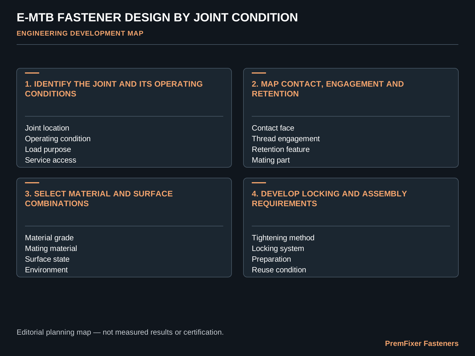
Identify the joint and its operating conditions
Describe the installation location, intended load purpose, contamination, vibration environment and service access for the actual platform. That avoids turning a general high-load narrative into an unsupported design value.
Build the working record around Joint location, Operating condition, Load purpose and Service access. The practical output is an application statement for the selected e-MTB joint.
For the "Identify the joint and its operating conditions" review, put installation interface, contact path, thread engagement, locking condition on the same sheet. Name the current revision, the decision owner and the condition that allows the part or program to move forward. The technical discussion then has a clear purchasing and release action.
Do not apply a uniform load multiplier to every e-MTB fastener.
Map contact, engagement and retention
Show which surfaces locate and carry contact, where the threads engage and how the fastener is retained. Thicker sections or altered thread forms are options only after these functions are known.
Keep the review anchored to Contact face, Thread engagement, Retention feature and Mating part. The practical output is a joint-interface map with candidate design questions.
Under "Map contact, engagement and retention," compare the current and proposed conditions using Contact face, Thread engagement, Retention feature, Mating part. Record the evidence source and any item that remains open. The buyer should be able to approve, reject or sample a specific supplier proposal.
Do not add material or thread length without checking space, assembly and the mating component.
| Review stage | Project question | Inputs to connect | Expected output |
|---|---|---|---|
| 01 | Identify the joint and its operating conditions | Joint location / Operating condition / Load purpose / Service access | an application statement for the selected e-MTB joint |
| 02 | Map contact, engagement and retention | Contact face / Thread engagement / Retention feature / Mating part | a joint-interface map with candidate design questions |
| 03 | Select material and surface combinations | Material grade / Mating material / Surface state / Environment | a material-and-finish option matrix for the defined joint |
| 04 | Develop locking and assembly requirements | Tightening method / Locking system / Preparation / Reuse condition | a proposed assembly-condition specification |
| 05 | Link the proposal to prototype learning | Sample revision / Manufacturing check / Assembly check / Program validation | a prototype task list with clear ownership |
| 06 | Define the e-MTB development package | Installation model / Mating parts / Intended use / Development quantity | a scoped e-MTB fastener engineering proposal |
Select material and surface combinations
Connect material strength, machining behaviour, mating materials, corrosion exposure and appearance rather than choosing from a label alone. The delivered interface includes the surface state as well as the base alloy.
Put the following fields on the same revision-controlled page: Material grade, Mating material, Surface state and Environment. The practical output is a material-and-finish option matrix for the defined joint.
In "Select material and surface combinations," follow installation interface, contact path, thread engagement, locking condition through the relevant handoff. The output from one operation or team should be a usable input for the next. Missing ownership at that boundary often causes more disruption than the operation itself.
Higher nominal strength does not automatically improve the complete assembly.
Develop locking and assembly requirements
Define tightening, locking, preparation and service around the full joint configuration. The vehicle category cannot supply a universal torque or locking answer.
Build the working record around Tightening method, Locking system, Preparation and Reuse condition. The practical output is a proposed assembly-condition specification.
Use installation interface, contact path, thread engagement, locking condition to define the sample question for "Develop locking and assembly requirements." The sample record should state what represents production, what is temporary and which decision follows the review. A conforming sample without that context can still leave the production route unsettled.
Keep any numeric parameter subject to the approved configuration and development method.
Link the proposal to prototype learning
Assign the prototype questions across structure, manufacturing, assembly and the vehicle-level work owned by the program. A machined component can meet its drawing while the joint still needs assembly and application review.
Keep the review anchored to Sample revision, Manufacturing check, Assembly check and Program validation. The practical output is a prototype task list with clear ownership.
After "Link the proposal to prototype learning," carry installation interface, contact path, thread engagement, locking condition into repeat orders and service planning. Approved conditions should remain visible in stock, inspection records and packaging so that later lots do not depend on personal memory.
Do not describe CNC completion as proof of vehicle durability.
Define the e-MTB development package
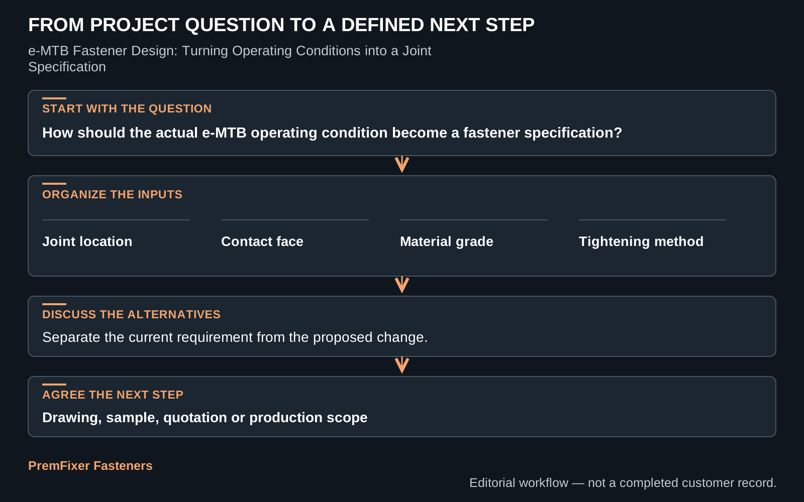
Bring the installation model, mating parts, intended use and quantities into one development package. This lets the first discussion identify open geometry and documentation without assuming a complete redesign.
Put the following fields on the same revision-controlled page: Installation model, Mating parts, Intended use and Development quantity. The practical output is a scoped e-MTB fastener engineering proposal.
Convert the result of "Define the e-MTB development package" into a quotation line that identifies installation interface, contact path, thread engagement, locking condition. Ask the supplier to state included work, customer inputs, open assumptions and release evidence. Alternative offers are easier to compare when scope is not hidden inside one unit price.
Start with a representative joint when the wider platform is still evolving.
Turn the comparison into a controlled work package
A motorized full-suspension platform combines tight access, heavier loads and frequent maintenance. Map that case from customer input to accepted delivery, including every point where the part, information or approval changes hands.
For each e-mtb fastener design: turning operating conditions into a joint specification handoff, write the input, responsible person, expected output and rejection condition. This short record makes schedule and responsibility visible without a large process manual.
Using a generic bicycle part can leave tool, locking or bearing-stack requirements unresolved. Compare the proposed controls with the current route and choose evidence that can reveal the difference during a representative sample or pilot.
Once the result for e-mtb fastener design: turning operating conditions into a joint specification is accepted, update the released files and any stock or service identity affected by the change. Keep superseded material separate whenever interchangeability has not been approved.
Provide the platform mass, joint section, motor and suspension packaging, materials, service and sample stage. A useful supplier reply links technical questions, commercial scope and release evidence to the same project revision.
Questions buyers ask
Where should the engineering review begin?
Convert higher mass, motor packaging and service conditions into joint-specific hardware inputs. The comparison is credible only when every option uses the same part revision, quantity and delivered condition.
What information should the supplier receive?
The first package should contain the platform mass, joint section, motor and suspension packaging, materials, service and sample stage. It should also state the immediate decision the customer needs from the supplier response.
What must a prototype demonstrate?
Base the pilot on this situation: a motorized full-suspension platform combines tight access, heavier loads and frequent maintenance. Record the representative operations and the approval that follows the result.
Which handoff deserves extra attention?
The main risk is that using a generic bicycle part can leave tool, locking or bearing-stack requirements unresolved. Put one person in charge of the related drawing, handoff or release action.
What output should the RFQ request?
For e-mtb fastener design: turning operating conditions into a joint specification, PremFixer can organize the files and open points into a manufacturing, sample and quotation response for the defined component or hardware set.
Review the e-MTB joint conditions
Share the platform mass, joint section, motor and suspension packaging, materials, service and sample stage. The response will identify the proposed scope, open questions and the evidence needed before release.
Discuss This Project