
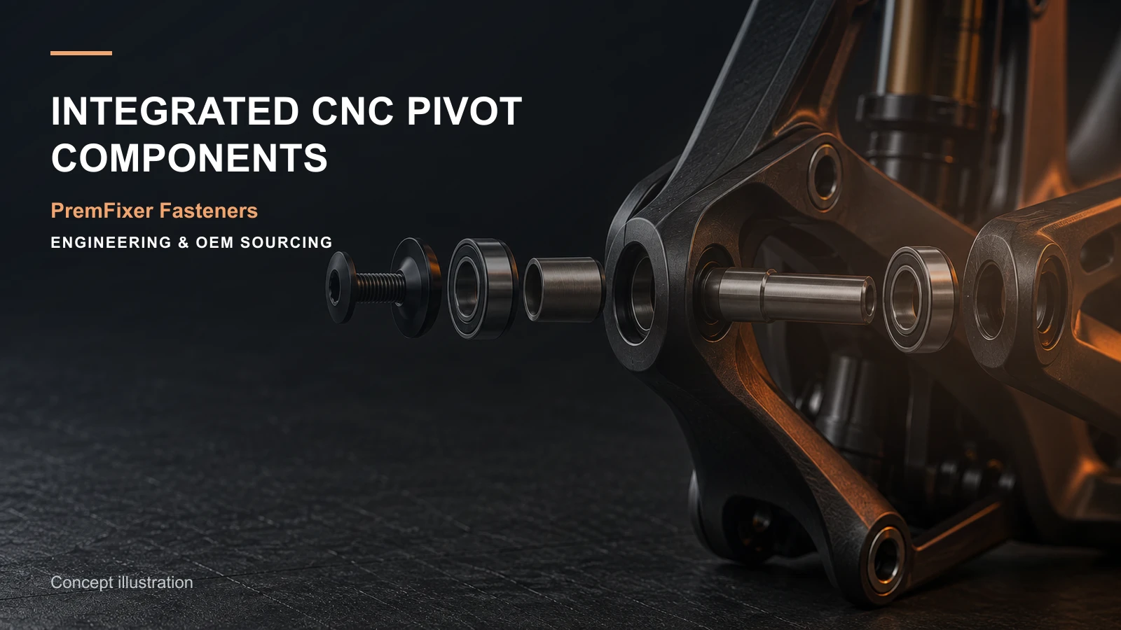
Integrated CNC pivot components combine functions that might otherwise be split across an axle, sleeve, spacer, nut or cosmetic cap. For a full-suspension frame, consolidation can reduce loose parts, simplify assembly and improve control of related diameters and faces. It can also create a more expensive component, difficult tool access or a service problem if the integration is not tied to the joint architecture.
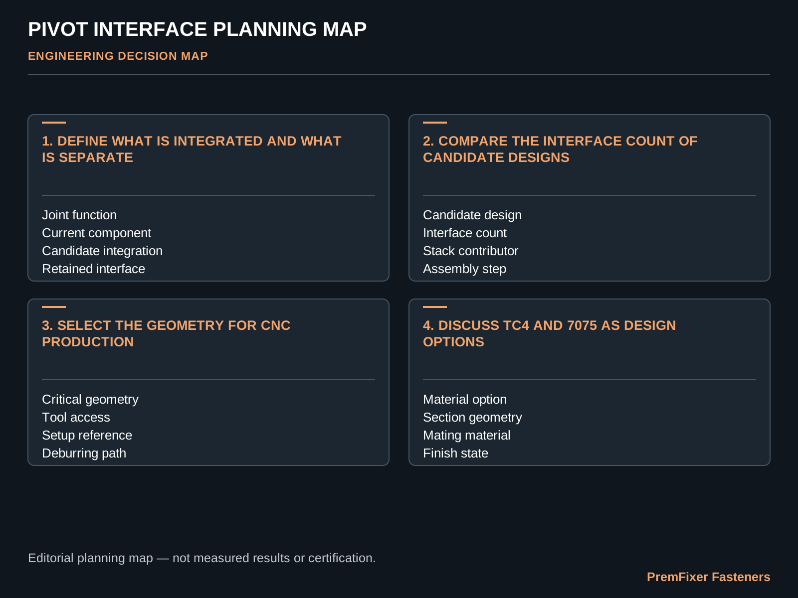
The decision should begin with the bearing and clamp stack, not with a desire to make the part look more sophisticated. Map which surfaces locate, support, clamp, seal, retain or provide tool access. Then compare an integrated concept with a conventional multi-part arrangement using the same functional requirements.
This guide focuses on the engineering and manufacturing questions that determine whether an integrated pivot component is a useful solution for a particular frame.
Map the pivot stack and load path
Document the frame tabs, linkage plates, bearing inner rings, sleeves, spacers, seals and retention elements in axial order. Mark which faces carry clamp load, which diameters locate the rotating assembly and which clearances allow the joint to articulate without side loading.
An integrated axle may combine a bearing-contact shoulder, spacer and threaded retention feature, but the merged geometry still has to respect the original functions. A clean section view with datum references is more useful than an isolated rendered part.
Include tightening direction and tool approach. A component that packages neatly in CAD may be impossible to hold, torque or remove once the shock, motor or adjacent linkage is installed.
| Interface | Design question | Manufacturing implication |
|---|---|---|
| Bearing contact | Which diameter and face locate the inner ring? | Control size, relationship and finish after processing |
| Clamp stack | Where does tightening force close the joint? | Protect shoulder length and contact faces |
| Retention | How is loosening prevented and serviced? | Define thread, tool access and locking method |
| Frame access | Can the part be installed and removed in the built bicycle? | Check head form, recess and removal path |
Compare integrated and multi-part architectures
List the current components and the function of each, then show which functions move into the integrated concept. Count interfaces, unique part numbers, assembly orientations and opportunities for incorrect mixing. Also note which individual items can no longer be replaced separately.
Integration can improve concentric relationships when related features are produced from one setup, but only if the machining plan and datums support that relationship. A longer or more complex part can also reduce material yield, extend cycle time and make finishing or inspection harder.
Use a side-by-side assembly drawing and a delivered-cost model. Part-count reduction is valuable only when it improves the complete program.
Select material by component role
An integrated component may contain surfaces with different demands: threads, bearing contact, cosmetic exposure and low-mass sections. Compare candidate materials against the whole set of functions rather than density alone. State grade and condition, not only a family name.
Titanium, alloy steel, stainless steel and aluminium each lead to different geometry, surface, galling, corrosion-pair and finishing questions. The correct choice depends on the actual joint, service practice and validation plan.
If material substitution is being considered, keep geometry and material changes separate where possible during early evaluation. Changing both at once can make sample results difficult to interpret.
Design for machining and inspection
Review stock size, workholding, tool reach, internal corners, cross holes, thread runout and the sequence needed to maintain critical relationships. Features on opposite ends of a long axle may require multiple setups; define how the functional datums will be transferred.
Plan inspection while the design is still flexible. Bearing diameters, shoulder distances and runout relationships need accessible measurement methods. If a recessed feature cannot be measured directly, agree on a functional gauge or alternative control before production.
Avoid hiding inspection difficulty inside a general tolerance note. The drawing should make the most important relationships visible to both machinist and quality engineer.
Prototype the assembly, not only the part
Check the integrated component in the actual or representative frame stack. Review insertion path, tool access, tightening sequence, bearing behaviour, clearance through suspension motion and removal for service. A dimensionally conforming part can still expose an assembly conflict that was invisible in isolation.
Use the sample report to connect measured features to these checks. Record whether the sample uses production material and finish, and identify any temporary conditions.
If the design replaces several parts, compare assembly time and error opportunities during a small pilot. The result should show whether integration produces a genuine line-side benefit.
Prepare an integrated pivot RFQ
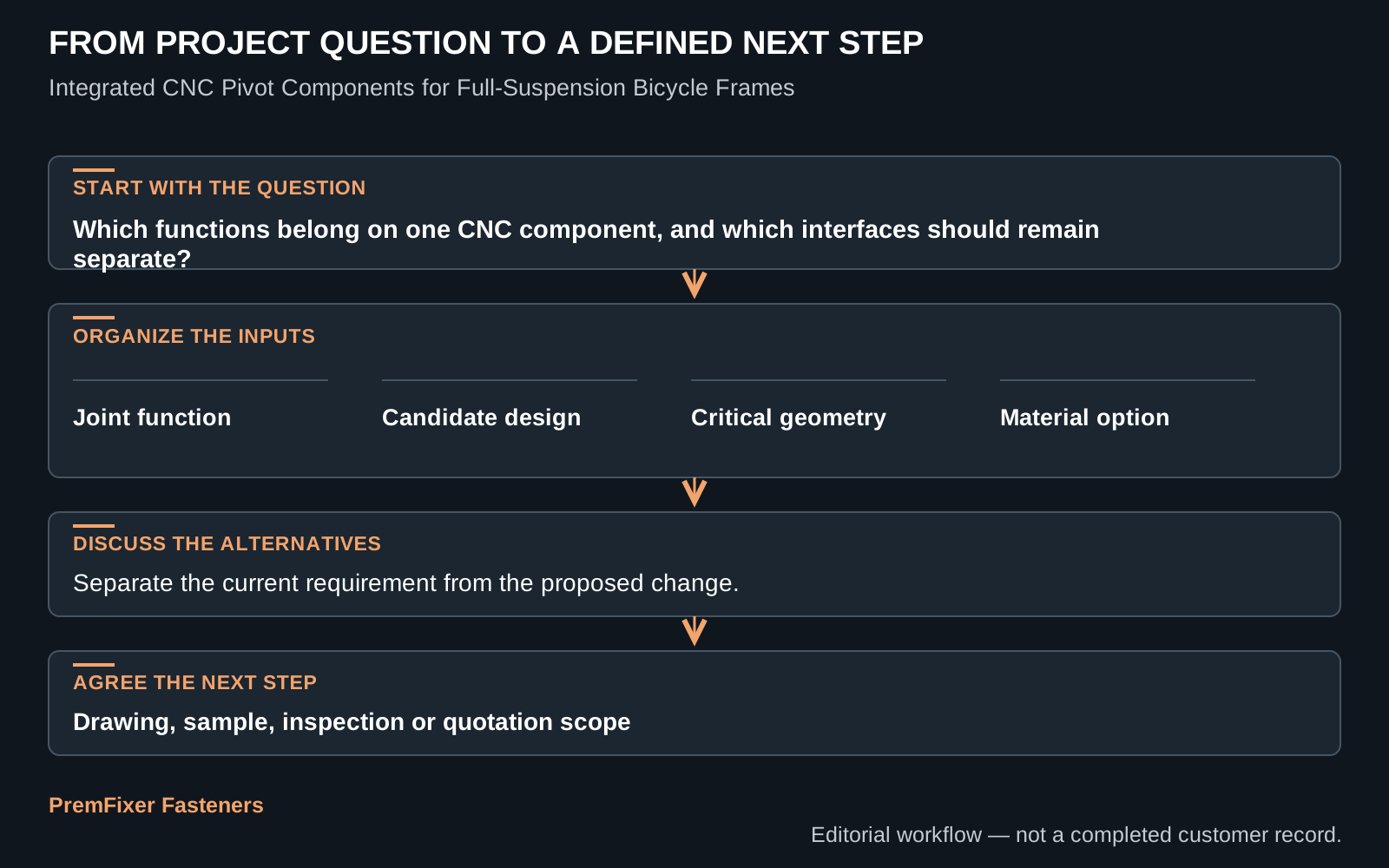
Provide the frame and linkage section, bearing arrangement, current component stack, candidate integrated geometry, annual and batch volume, material direction, finish, tool envelope and service requirement. Identify the interfaces that are fixed and the areas open to DFM feedback.
Ask the supplier to respond with a process route, datum and inspection proposal, open-question list, sample condition and options that preserve the joint function. If the concept is intended to reduce parts or assembly work, request that the quotation clearly defines the delivered kit.
PremFixer can review CNC pivot axles, sleeves, spacers and related hardware as an assembly. A section view and current BOM are the fastest starting point for deciding whether integration is worthwhile.
Compare service and failure isolation before consolidating parts
A multi-part pivot allows selected items to be replaced independently. An integrated axle may require replacement of a larger and more expensive component when one thread, cosmetic face or wear area is damaged. Compare the likely service events and decide whether the assembly benefit justifies that coupling.
Identify how a mechanic will recognize the correct part and orientation. Model-specific integrated hardware should have a stable part number, revision identity and kit description. If two axles look similar but differ in shoulder length or thread, packaging and service documentation need to prevent interchange errors.
Consider inspection and problem isolation as well. With separate parts, a spacer or sleeve can be measured and replaced independently. With integrated geometry, the supplier may gain control of concentric features but must also diagnose the whole component when one relationship fails.
Use a simple service scenario during design review: remove the joint after normal use, identify the necessary tools, replace the intended wear or damaged item and rebuild it without factory-only fixtures. Record any surface that is likely to be marked or any feature that becomes inaccessible in the complete bicycle.
The result may support full integration, partial integration or retention of a replaceable sleeve or nut. The strongest design is not the one with the fewest pieces; it is the one that balances assembly control, manufacturability and the service life of the complete frame platform.
Questions buyers ask
What is an integrated CNC pivot component?
It is a drawing-controlled machined part that combines two or more functions—such as axle, shoulder, spacer or retention features—that might otherwise be supplied as separate components.
Does part consolidation always reduce cost?
No. It can reduce purchasing and assembly work, but complex geometry, lower material yield, longer machining or less serviceability can offset those benefits.
Which files are needed for a pivot review?
Provide a section of the frame and linkage, bearing details, current stack, tightening and tool direction, material and finish direction, quantities and service requirements.
How should an integrated pivot be prototyped?
Inspect the part and assemble it in a representative joint. Check fit, clamp stack, tool access, motion clearance, removal and the specific questions identified before sampling.
Can titanium or aluminium replace steel in an integrated axle?
They may be candidates, but the choice requires component-specific review of geometry, interfaces, material condition, finish, assembly and validation. Density alone is not sufficient.
Review the Complete Pivot Stack
PremFixer can compare an integrated CNC concept with the current multi-part arrangement before you release the production drawing.
Request a Pivot Review