
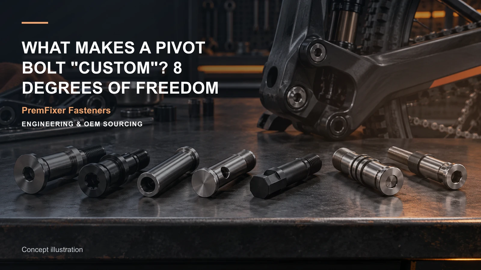
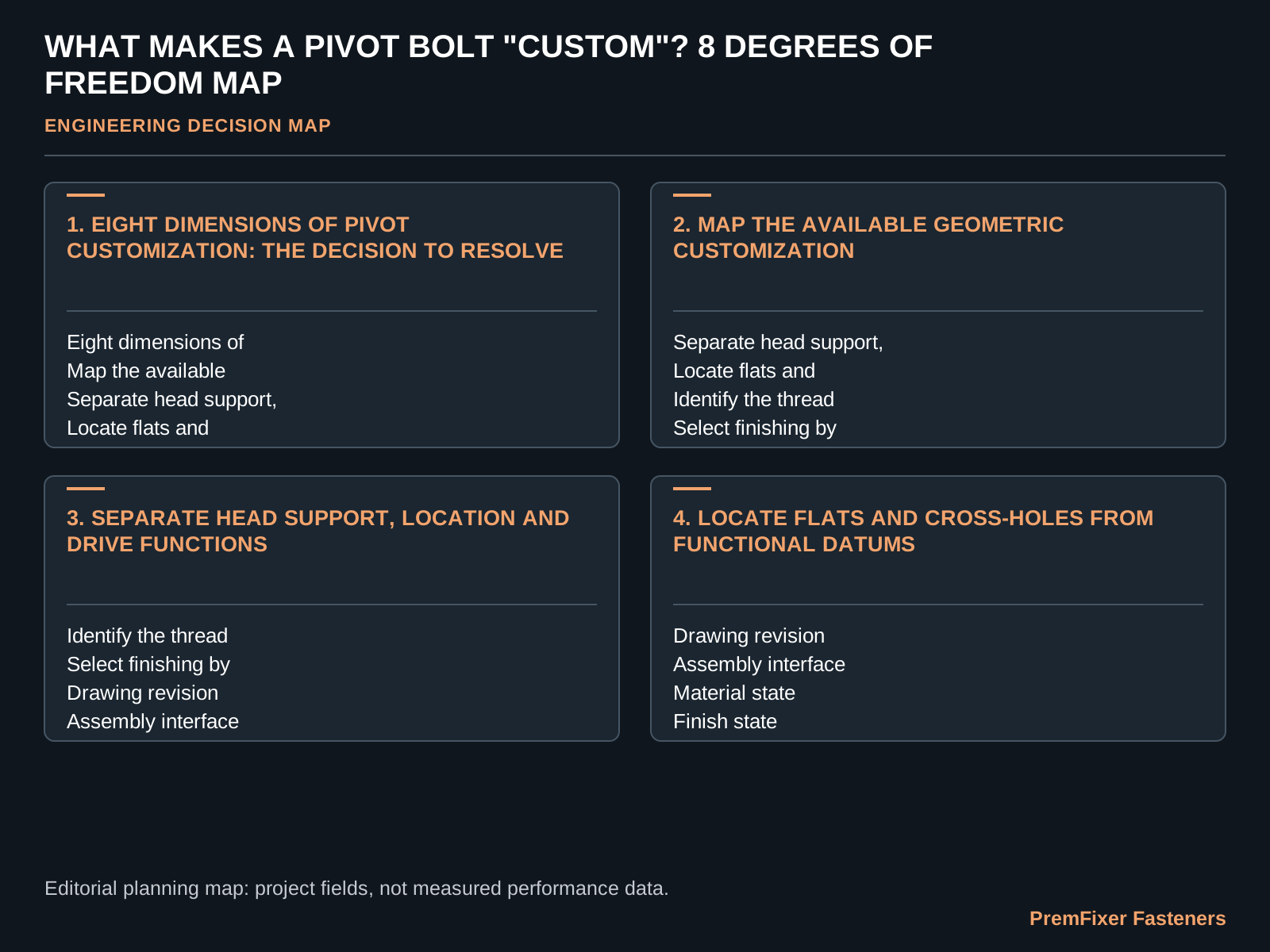
A pivot bolt can be customized in at least eight practical ways: length, diameter, head, flat, cross-hole, groove, thread and surface condition. The useful question is not how many features can be added, but what each one does in the bicycle joint. A longer shoulder may change the clamp stack; a cross-hole may remove material near a loaded section; a finish may alter a critical fit. OEM engineering should assign a function and acceptance check to each requested feature before manufacturing quotes the geometry. This keeps styling, assembly access and structural interfaces from being mixed into one unexamined specification.
Length and diameter control the working interface
Overall length and shoulder span are different dimensions. The shoulder may locate a bearing inner ring or sleeve, while the threaded end provides clamp force. A diameter change can alter bearing fit, wall thickness, machining stock and the required gauge. Specify the surface that actually mates, its datum and the allowable variation rather than tightening every diameter equally.
An ISO metric thread designation names a thread, not the full pivot geometry. Keep thread engagement and thread runout away from an intended bearing or sleeve contact unless the design expressly accounts for them.
Head, flat, hole and groove need separate purposes
The head provides tool access and a bearing face. A lower head can improve clearance but changes drive depth and available material. Flats may orient a part or resist rotation; their position should be referenced to the mating feature. A cross-hole can accept a retainer. A groove might hold a clip or seal, or form part of a deliberate lubrication path, but its location and depth interrupt the local section.
Before selecting any secondary feature, show the surrounding frame, tool envelope and load direction. A proposed oil groove also needs an actual lubrication strategy and sealing path; a groove alone does not improve wear. Ask whether a separate washer, sleeve or retention part would meet the same need with less interaction on the bolt.
Manufacturing process · Nonstandard size decisions
| Feature | Use condition | Interaction risk | Verification |
|---|---|---|---|
| Shoulder length or diameter | Locating or spacing a mating component | Fit or clamp path shifts | Assembly stack and controlled seat measurement |
| Head or drive | Tool access within a frame envelope | Reduced drive engagement or contact area | Tool and head-face check in assembly |
| Flat, hole or groove | Orientation or retention | Interrupted loaded section | Section review and first-article location |
| Thread | Required clamp and mating engagement | Runout enters a functional seat | Thread gauge and assembly check |
| Surface condition | Appearance, corrosion or contact duty | Finish affects fit or sliding behavior | Finish specification and post-process measurement |
Thread and surface choices affect different interfaces
Define thread form, pitch, class, length and mating part before choosing how it will be made. Thread rolling and machining are manufacturing routes with different tooling and geometry implications; neither can be selected from nominal diameter alone. Keep the threaded portion and any undercut visible in the assembly model.
Specify surface treatment by substrate, exposure and contact location. An appearance finish on an aluminum head should not be assumed suitable for a bearing seat or sliding surface. The drawing should identify masked or post-finish dimensions where the finish changes fit.
Material selection · Surface treatment scope
Illustrative engineering example: assume an OEM wants a lower head and a cross-hole for a retaining clip on one pivot. The head improves frame clearance, but the hole would sit near the shoulder-to-thread transition. The team first tests whether the clip can sit on a separate sleeve, then checks remaining section and tool access on the proposed bolt. A drawing and first-article measurement would follow only after the retention choice is made. No load result is implied.
Resolve feature interactions before a sample
Create a feature-function map with one row per changed element. Check whether a cross-hole intersects the shoulder transition, whether a groove approaches a load-bearing edge, and whether a head modification leaves the intended drive accessible. Use the real mating assembly rather than an isolated render.
The first article should confirm the specific geometry and assembly effects that made the feature necessary. Do not use an attractive sample as proof of load capacity or fatigue life without a separate approved validation plan.
Quote a controlled feature set
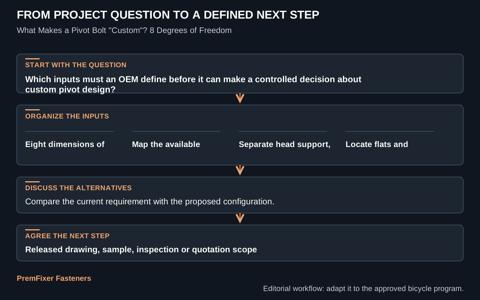
PremFixer Fasteners can review CNC machining, cold-heading, thread-rolling or tooling feasibility against the supplied drawing. Features that need partner surface treatment or testing are quoted within the agreed route. The OEM should identify which features are essential, which are optional and which appearance choices can be deferred.
Send a dimensioned drawing, STEP assembly, mating-part details, material and finish specification, quantities and intended inspection points. The reply can then address the actual feature interaction instead of a generic custom-bolt request.
Questions buyers need to resolve
Can all eight features be changed at once?
They can be specified, but that does not make the combination suitable. Check each feature's purpose, neighboring geometry, machining access and joint load before accepting a combined drawing.
Does a different head require a new pivot diameter?
No. Head access and shoulder fit are separate requirements. Preserve the approved bearing or sleeve seat unless a joint analysis shows that diameter also needs changing.
Where should a cross-hole be located?
Locate it from a functional datum and outside critical contact or loaded transitions where possible. Supply the mating retainer geometry and load path so the hole position can be reviewed.
Can finish thickness be ignored on the shoulder?
No when the shoulder is a controlled fit. State whether the tolerance applies before or after finishing and whether the working surface is treated, masked or finished to size afterward.
What should an eight-feature RFQ include?
Provide the drawing, STEP assembly, feature-function notes, mating parts, material, finish and order quantity. Mark essential features and optional styling so manufacturing can quote a realistic route.
Review the Features That Matter
Send the drawing, STEP assembly, mating components and a short purpose for each changed feature. PremFixer can review geometry, process access and inspection points before quoting the defined pivot bolt.
Discuss the drawing and BOM