
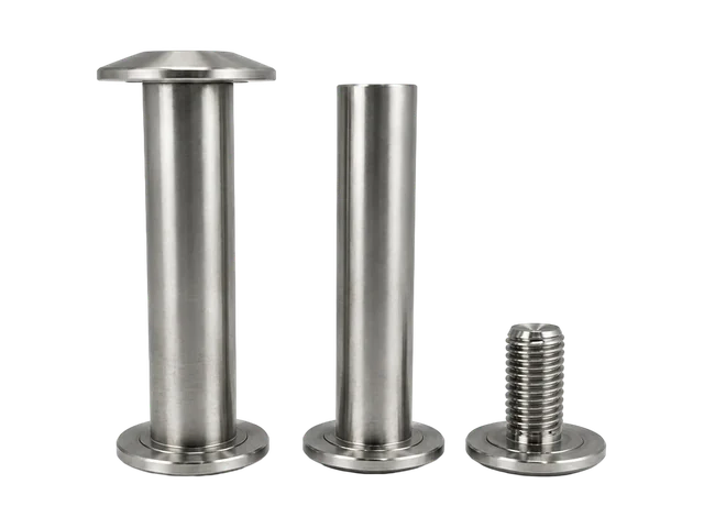
Existing PremFixer product reference
Flanged sleeve and locking screw reference
Existing bicycle hardware shown to explain separate component identities and contact surfaces.
View original record →Assembly function / Fit and retention
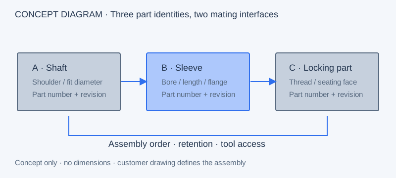
Matched shaft, sleeve and locking assemblies bring several individually defined components into one fit and retention review. PremFixer uses the complete mating drawings to assess shoulder positions, sleeve lengths, diameters, threads and installation access. Identify each part and revision, then show how the components locate, retain and release within your approved assembly.
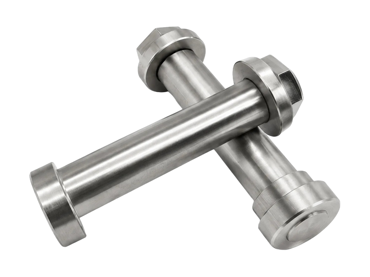
The shaft may establish position through a shoulder or a fitted diameter. The sleeve can provide a bearing surface, a contact length or a separate interface to the surrounding structure. A locking screw or nut retains the relationship through its thread and seating face. Naming those roles helps distinguish a paired manufacturing requirement from three unrelated component quotations.
Show both the assembled state and the order in which parts enter it. A shoulder may limit insertion before a flange seats; a recessed fastener may require access before a surrounding bracket is installed. These relationships should be visible in the customer’s assembly drawing rather than inferred from a loose-parts photograph.
The existing component groups below illustrate flanged sleeves, paired pivot geometry and accessible locking features. Their bicycle origin remains explicit. They provide a way to discuss a new interface without changing the identity of the original parts.
Existing bicycle hardware shown to explain separate component identities and contact surfaces.
View original record →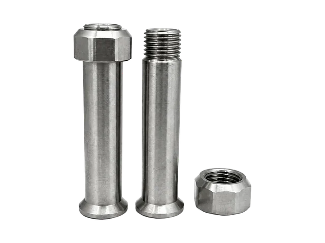
A reference for drive access and paired threading, retaining its original bicycle application.
View original record →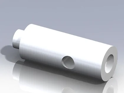
A shaft geometry reference for shoulder location, radial features and the relationship to a mating component.
View original record →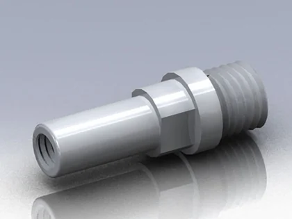
Reference for mating threads, stepped diameters and tool access. Its original identity remains Pivot Shaft.
View original record →Identify the diameter pair that establishes fit and the end faces that limit axial movement. Then show the thread, retaining feature or other approved method that holds the components in position. A fit dimension on one part should identify the drawing and revision of its mate.

The PS-P02 Pivot Shaft reference includes a shoulder and radial feature. Its original drawing shows why the relationship between features matters, beyond a single overall length. Use the customer drawing to define the required datum, radial feature position and orientation for a new assembly.
The separate PS-P04 Pivot Shaft record includes internal and external threads with wrench flats. Where those feature types matter, supply the tool envelope and identify which thread or face controls retention. The original dimensions belong to the reference components and should not be transferred to another assembly.
The shaft and sleeve can have separate material and surface requirements. Discuss the customer’s specified combination through the materials guide, identifying finished fit surfaces and any excluded coating areas. Colour in a reference photograph does not establish the material or treatment needed for the new set.
Plan inspection in two layers: measurements against each component drawing, followed by the agreed paired check. Name the mating samples, finish state and customer acceptance conditions before sampling. These records distinguish a dimensional result from an assembly assessment and make a later engineering change easier to review.
If one member changes revision, list every affected mating item, even where its own drawing remains unchanged. Changes to the shoulder, flange thickness, thread engagement or surface condition may require a fresh paired sample review. Use the fastener system manufacturing page for the wider BOM, packing and repeat-order scope.
Send the full mating set, with an exploded view or a clear assembly sequence. Identify open interfaces so the quotation can separate confirmed requirements from decisions awaiting approval.
Supply the drawings for all interfaces that govern the requested components. A customer-supplied mating item can remain outside the quotation, but its relevant dimensions, revision and role are still needed for the paired review.
Put each part number and revision on a shared assembly register. Name the mating revision beside the interface or assembly reference. When one drawing changes, identify the full affected combination and the customer approval needed before repeat supply.
Different conditions can be reviewed per component. State the approved material and finish on each drawing, which surfaces mate and whether dimensions apply after treatment. The accepted combination should be included in the sample plan.
Show the feature that prevents the intended axial or rotational movement, its mating geometry and installation condition. Include thread engagement or a separate retaining part where relevant, plus the drive access and removal sequence specified by the customer.