
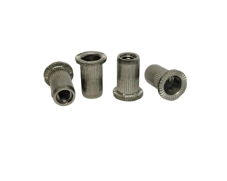
Existing PremFixer product reference
PS-F01 Aluminum Knurled Rivet Nut
Original rivet-nut reference for a customer-specified mechanical installation and host opening.
View original record →Assembly function / Threaded host interfaces
A threaded insert creates an attachment interface in a customer-defined tube, bracket or frame member. PremFixer reviews the requested threaded hardware together with the host material, opening, contact surfaces and specified installation method. Start with the approved installation concept, then identify the loose-component supply scope and the requirements that apply to the installed connection.
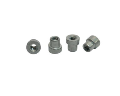
A weld-in nut and a mechanically installed rivet nut are different interfaces. Their review starts with the installation method already specified for the host member, rather than treating every flanged threaded part as interchangeable. Provide the host material, relevant wall or contact region and the opening into which the component is fitted.
The host drawing should show accessible sides and the neighbouring features that restrict installation or fastening. Identify whether the threaded component sits against a flange seat, enters a recess or uses another approved contact arrangement. A loose insert photograph cannot define that installed relationship by itself.
The PS-E01 hero is the existing weld-in nut. These PS-F records show different rivet-nut forms, with their original names and URLs preserved. Each reference stays linked to its own record; the project drawing defines the chosen installation and host interface.
Original rivet-nut reference for a customer-specified mechanical installation and host opening.
View original record →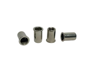
Original smooth-body rivet-nut record; the host and installation requirements remain project-specific.
View original record →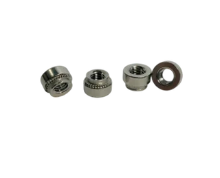
A large-flange threaded component reference. Match its host and installation requirements to the approved drawing.
View original record →Show the interface in section. Include the host opening, wall or contact region, flange seating surface and the direction in which the mating fastener enters. Identify the usable thread in the intended installed state, together with any restriction created by the host or adjacent component.
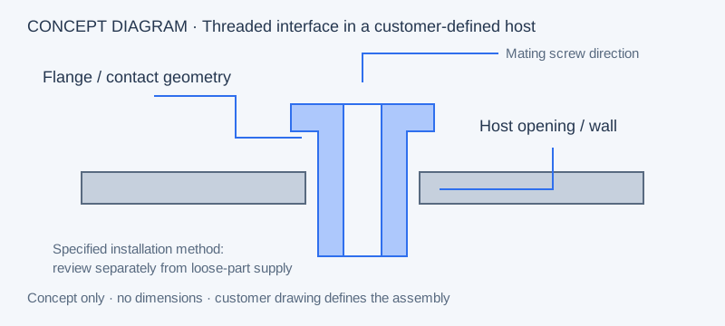
A quotation can identify the loose threaded hardware while the customer retains host fabrication and installation. If additional work is requested, name it explicitly and confirm the available scope. This keeps the component drawing, installation specification and installed-joint acceptance connected without assuming they are one operation.
| Review item | Required definition | Supply / acceptance responsibility |
|---|---|---|
| Loose insert | Drawing, thread, material and finish | Confirm in the component quotation |
| Host member | Material, opening and contact region | Identify customer-supplied or separately quoted scope |
| Installation | Specified method, access and process sequence | Welding, tooling or installation work requires separate confirmation |
| Installed connection | Customer-defined fit and functional checks | Agree who performs and approves the required validation |
State whether surface treatment occurs before or after installation and which requirements apply to the supplied component. This matters when the final contact area or usable thread is established only after the host process. The existing manufacturing process and materials pages support the route discussion; the actual sequence is project-specific.
Agree inspection of the loose component separately from assessment of the installed connection. Any required pull-out, rotation or other functional test needs the customer’s method, conditions and responsibility. For samples, identify the host specimen and mating fastener used, along with the insert revision and finish state.
The existing aluminum bicycle-frame solution remains the route for that specific application. This page addresses the broader procurement question of a defined threaded host interface. Static stand-off distance is covered separately by mounting spacers and standoffs.
Provide the insert drawing and host section together. State the intended installation method and distinguish the loose hardware request from any additional operation or validation requirement.
That change requires the customer’s design review. Weld-in and mechanically installed interfaces have different host and process requirements. Identify the approved installation method and provide the related drawings before considering an alternative.
Provide the opening, wall or contact region, seating geometry and relevant position reference. Include surrounding restrictions and accessible sides. These inputs connect the loose-component dimensions to the intended installed interface.
The quotation should state this explicitly. Loose insert supply, host fabrication, welding, mechanical installation tooling and installed-joint testing are separate responsibilities to confirm. List any additional operation requested instead of assuming it follows from the product name.
The customer’s approved installed geometry, mating fastener and process sequence define it. Show the required engagement and any host or coating restriction, then identify which checks apply to the supplied insert and which apply after installation.