
CNC Turning
We machine outside diameters, steps, shoulders, end faces, axial holes, suitable bores, grooves and threads. These rotational features define the working surfaces of shafts, shoulder bolts, sleeves, spacers and flanged components.
Custom Fasteners & Precision Turned Components
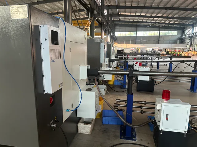
PremFixer Fasteners manufactures custom fasteners and precision turned components using CNC turning and turn-mill machining. We produce drawing-defined shoulders, stepped diameters, bores and threads, together with milled features such as cross-holes, slots and wrench flats. Our production supports OEM fasteners, pivot hardware, shafts, sleeves and spacers from prototypes to repeat orders.
View ISO 9001 Certificate
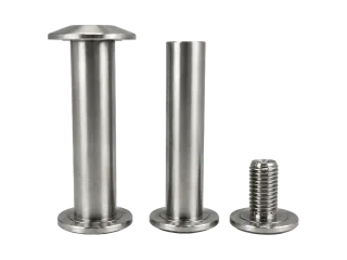
PremFixer Fasteners is a China-based manufacturer established in 2020. Our CNC turning service connects part geometry, drawing references and assembly requirements.
We machine outside diameters, steps, shoulders, end faces, axial holes, suitable bores, grooves and threads. These rotational features define the working surfaces of shafts, shoulder bolts, sleeves, spacers and flanged components.
We combine turned geometry with cross-holes, slots and wrench flats. Feature position, orientation, tool access and workholding guide the operation sequence. The PS-P04 example illustrates the relationship between shoulders, threads and flats.
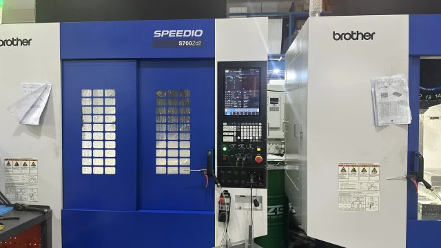
Dimensions, roundness, position and runout describe different requirements. Define each against the drawing references and the supplied condition.
| Feature | Manufacturing focus | Drawing & finished checks |
|---|---|---|
| Outside diameters & steps | Working diameters and stepped sections | Mating fits and relationships to adjacent features |
| Shoulders & seats | Shoulder lengths, faces and under-head seats | Axial position, mating thickness and contact faces |
| Bores | Axial drilling and suitable internal turning | Diameter, depth, bottom shape and tool clearance |
| Internal & external threads | Specified thread geometry | Standard, pitch, tolerance class and usable length |
| Grooves & reliefs | Circumferential grooves and tool relief | Width, depth, position and edge condition |
| Cross-holes | Transverse drilling | Location to datums and intersecting-hole deburring |
| Wrench flats | Flats and local milling | Across-flats dimension, orientation and tool space |
| Sleeves & thin walls | Wall section and clamping plan | Distortion after release and finished dimensions |
| Longer shafts | Support matched to length and diameter | Drawing-defined straightness and runout |
| Finished surfaces | Machining coordinated with treatment | Fits, threads, surface texture and appearance |
Thin walls, deep holes and long slender sections require geometry-specific process planning.
Geometry from the existing product library
Explore shafts and pivot hardware alongside spacers and turned components. Each reference helps describe a new drawing-defined part; its production route follows the approved order specification.
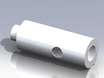
The cylindrical body, reduced-diameter step, axial end hole and cross-hole connect rotational and transverse features. Shaft diameter and shoulder position establish the mating interface; cross-hole location must relate to the same drawing references.
For a similar component, identify the functional diameter, axial location and hole-edge requirements together. The original drawing documents geometry, while the new order defines its material, tolerances and finished condition.
 Open original drawing ↗
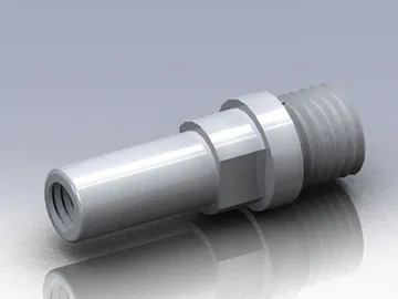
Stepped diameters, shoulders, wrench flats and internal and external threads share one shaft-style component. Flats provide installation tool access; shoulders establish seating positions, while threads provide the connection.
Our CNC turning and turn-mill capabilities support this combined geometry. Specify the relationship between the flats, shoulder faces and threaded sections, including usable thread length and tool clearance. The selected route connects those requirements to material and inspection, without assuming a single setup for this reference.
 Open original drawing ↗

The bore, outside diameter, thickness and two end faces define this spacer's interface with adjacent parts. A simple turned shape still needs a clear distinction between clearance surfaces and functional contact faces.
Specify the thickness that sets assembly spacing, the mating diameters and the edge condition. If the spacer receives a surface treatment, state which dimensions apply after treatment so that the supplied part preserves the intended distance and fit.
 Open original drawing ↗
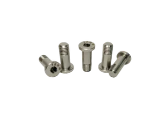
Countersunk seat, shoulder and partial external thread. Control seating and shoulder length together. The original record specifies 304 stainless steel.
Original product ↗Discuss a Similar Component ↗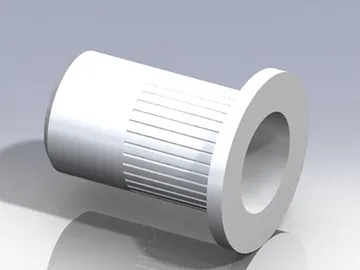
Flange, stepped body and center hole. Define the locating diameter and contact face for the mating interface.
Original product ↗Discuss a Similar Component ↗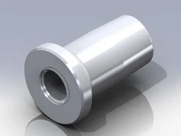
Sleeve body, flange and axial hole. Connect hole depth and wall section to the mounting interface and finished size.
Original product ↗Discuss a Similar Component ↗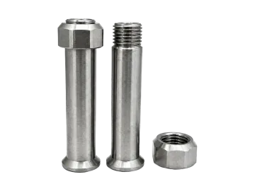
External hex drive and threaded shaft geometry. Define engagement, seating faces and quantities per assembly in one BOM.
Fastener system manufacturing ↗Discuss a Similar Component ↗The original drawings above open at full resolution. For a new part, keep manufacturing and inspection aligned with the assembly's reference system.
Specify grade and stock condition before comparing machining and finishing options. See our engineering materials guide for selection context.
Mark treated surfaces, masking and any post-treatment machining. Fits, bores and threads need explicit before- or after-treatment acceptance, alongside edge condition, surface texture and appearance. In-house machining is coordinated with qualified partners for surface treatment, heat treatment and specialist testing as the order requires.
 View English original ↗
The ISO 9001:2015 certificate covers the quality management system of Guangdong Pinshang Hardware Products Co., Ltd. within the stated scope: Production of hardware screws and nuts. It is a management-system certification, not product certification for every turned component.
Agree the drawing revision, material requirements and sample or first-off scope. Identify shoulder lengths, bores, threads, critical fits, finished dimensions and cross-hole burrs. Inspection reports and retained records follow the order agreement; repeat orders reference the approved revision.
Explore quality control ↗ Certificate details ↗Material and stock size, feature complexity, machining time, workholding, programming and tooling affect the quote. Quantity spreads preparation costs across the batch; treatment, inspection documents and packing add order-specific work. Compare quotes against the same scope and acceptance requirements.
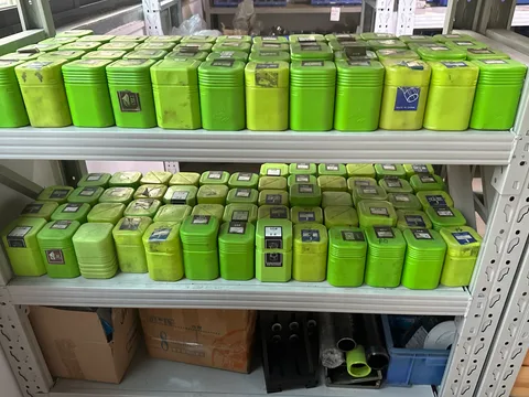
Pivot shafts, shoulder bolts, paired locking hardware, sleeves and spacers for drawing-defined frame assemblies.
Full-suspension pivot systems ↗Mounting spacers, threaded parts and shafts manufactured to the customer's drawings and application requirements.
Motorcycle components ↗Positioning, support, spacing and threaded interfaces across mating components.
Shaft, sleeve & locking assemblies ↗We manufacture custom fasteners, shoulder parts, pivot shafts, threaded shafts, sleeves, bushings, spacers and related OEM components. The examples on this page show existing geometries. For your order, the approved drawing defines the dimensions, material, mating interfaces, surface condition and acceptance requirements.
CNC turning primarily creates rotational features such as outside diameters, shoulders, faces, bores and threads. Turn-mill machining combines turned geometry with suitable cross-holes, slots and flats. Process planning connects the complete feature set to workholding, tool access and inspection references, including any additional operations the part needs.
Yes. Our CNC turning and turn-mill capabilities support parts combining rotational geometry with milled details. Show the position and orientation of cross-holes, flats or slots relative to the drawing datums. Those relationships, together with access and clamping requirements, determine the machining sequence and inspection plan.
Material options include 304 and 316 stainless steel, 6061 and 7075 aluminum, carbon and alloy steels, and drawing-specified titanium grades such as TC4 or Ti-6Al-4V. Specify the applicable standard, stock condition or temper, treatment and documentation requirements. Material selection must match the component's geometry and intended service.
Yes. Include the thread standard, size, pitch, tolerance class and effective engagement length. For blind internal threads, show hole depth and bottom clearance separately from usable thread length. Identify the mating thread and any treatment or masking requirement so that acceptance concerns the supplied, finished connection.
Tolerance capability depends on the feature, size, material, wall section, treatment and inspection conditions. Send the drawing with its functional fits and geometric requirements so we can confirm the production and measurement approach. A diameter tolerance does not replace separate requirements for roundness, position, straightness or runout.
Datums give manufacturing, assembly and inspection a common reference. Mating-part information shows which diameters locate, which faces seat and where clearance is needed. This helps connect shoulder positions, thread engagement and cross-feature locations to the actual assembly, rather than evaluating each dimension as an isolated number.
We manufacture sleeve and spacer geometries. Thin-wall requirements need a review of wall thickness, bore depth, material and clamping because the part can change shape when released. Show the functional surfaces and finished dimensions, including the measurement condition, so workholding and inspection address the supplied part.
Treatments can change the size or surface condition of mating features. Specify which dimensions apply after treatment, especially bores, bearing seats and threads. Define treated and masked surfaces and any permitted subsequent machining. Finish appearance, edge condition and surface texture should also be part of the acceptance criteria.
Yes. We support prototypes, small batches and repeat production. State what the sample must establish, such as fit, geometry or assembly clearance, along with material and critical requirements. Include both sample quantity and expected production quantity so the quotation can distinguish preparation work from subsequent manufacturing.
Repeat orders reference the approved drawing number, revision, material and finished requirements. Identify any changes to dimensions, treatment, inspection, mating parts or packing before production is arranged. Sample approvals and agreed records provide the order reference; an unchanged part name alone is insufficient to control an engineering change.
The certificate names Guangdong Pinshang Hardware Products Co., Ltd. and covers its ISO 9001:2015 quality management system for the production of hardware screws and nuts. It does not certify every product individually. The original certificate and scope are available above, together with the issuer and validity dates.
Yes. Share a BOM identifying each part number, drawing revision, material and quantity per assembly. Include mating drawings, finished interface requirements and the required packing relationship. Our fastener system manufacturing process connects shafts, sleeves, spacers, nuts and other related components to the same project definition.
Send the drawing and revision, material and condition, sample and production quantities, finish and critical acceptance requirements. Add mating drawings or a BOM where relevant, plus requested timing and inspection documents. If a detail remains undecided, identify it clearly so the quotation records the agreed basis.
Start with your part
Share your drawing, material and quantity. Include mating-part information or a BOM where the component belongs to an assembly, and identify the finished requirements that matter most to your project.
If a requirement is undecided, mark it for discussion. Keep sample quantities, production quantities and any requested preparation or tooling costs separate in the RFQ.
Prepare the RFQ package →