
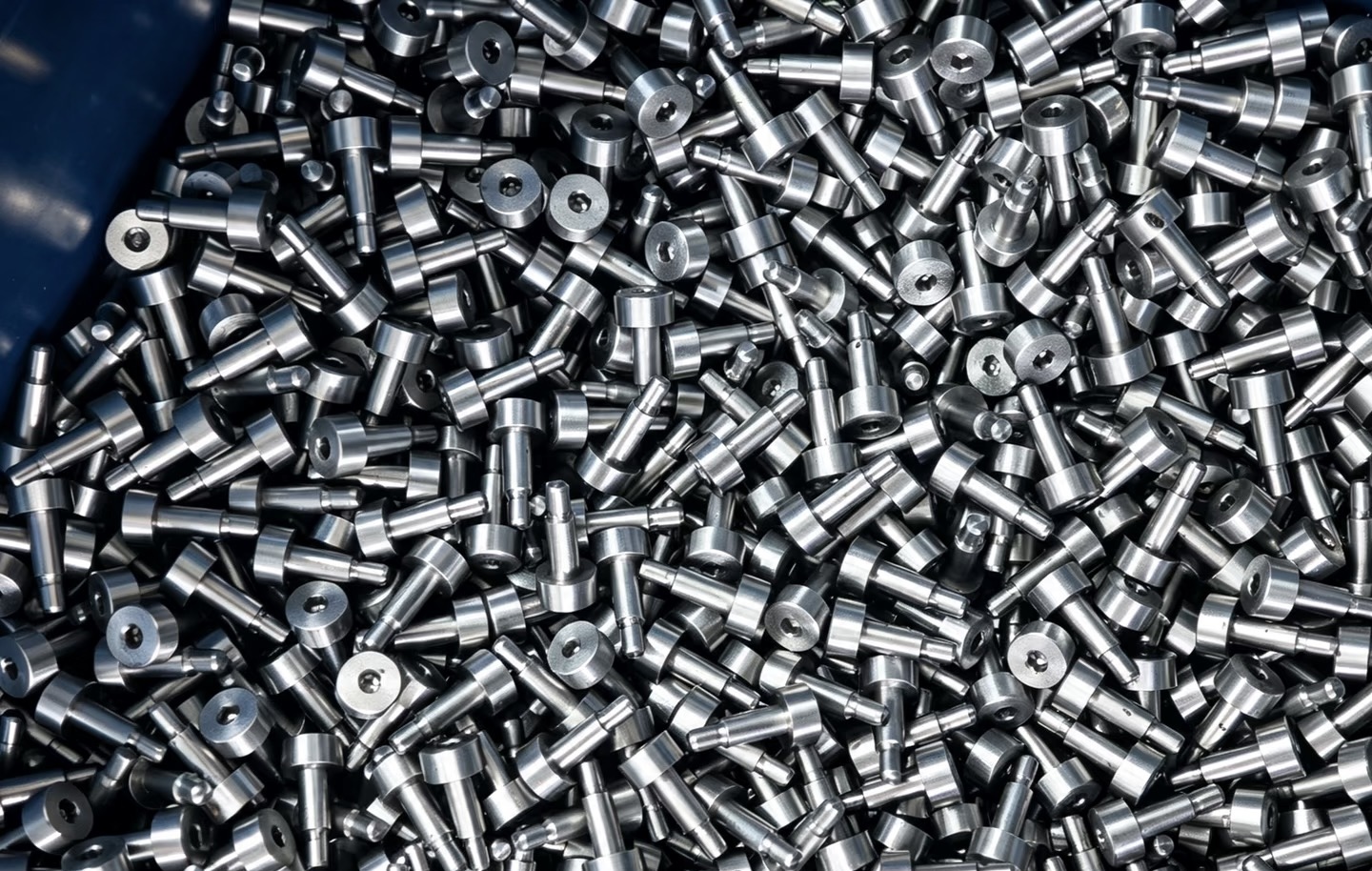
Stepped and flanged interfaces
Identify which shoulder locates the part, which diameter mates with a bore and which surfaces require inspection in the finished condition.
For automation and motion OEM projects
PremFixer manufactures custom pins, threaded adaptors, sleeves, spacers and fasteners for drawing-defined automation and motion-mechanism projects. Our CNC turning and turn-mill capabilities support shoulders, bores, threads, cross-holes and wrench flats. Send the interface drawings and required quantities for development, small-batch or repeat production.
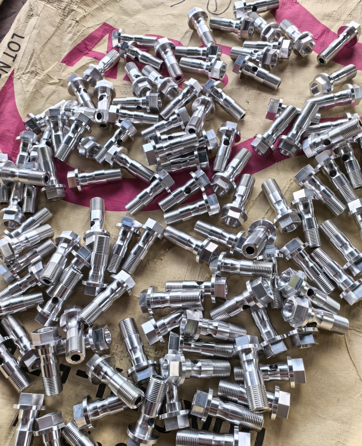
Define the individual components between the actuator and your mechanism: a connecting pin, threaded adaptor, sleeve, mounting spacer or fastener. Give each item a drawing and a clear place in the module BOM.
A connection pin needs a working section, mating holes and an agreed retention arrangement. A threaded adaptor needs both thread definitions and the references that orient any flats or cross-holes.
Mounting spacers and sleeves establish contact positions in the assembly. Show the loaded faces, insertion direction and relationships to the surrounding bracket or mounting plate.
These existing product photos and technical references explain manufacturable forms. They do not represent a supplied actuator, robotic module or validated motion system.
Identify which shoulder locates the part, which diameter mates with a bore and which surfaces require inspection in the finished condition.
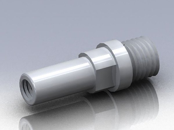
The PS-P04 bicycle-component rendering shows internal and external threads with a flat feature. Your adaptor drawing sets the sizes, orientation and engagement.
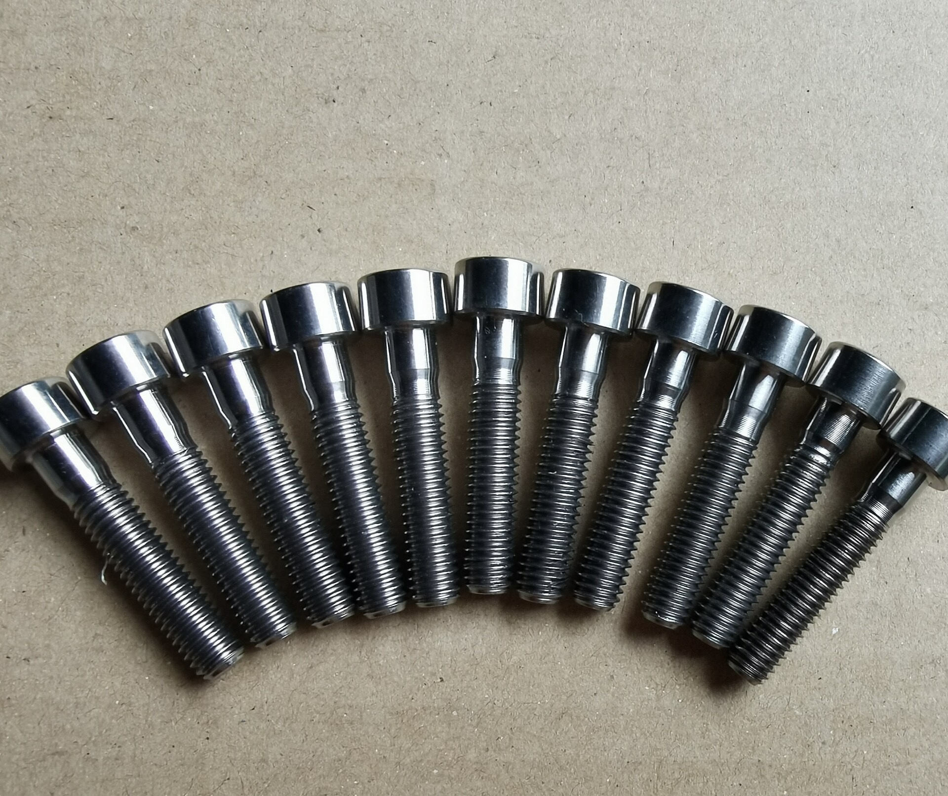
Specify the working length, drive access and contact surfaces. A pictured fastener is a geometry reference, not evidence of a particular motion load or cycle rating.
For an adaptor with wrench flats, identify the axis and face used to locate it. If flat orientation matters to the assembly, define its relationship to a hole, slot or other datum. Include the space available to tighten or remove the part.
Show nearby moving components in an assembly view. The envelope helps explain the design, while the part drawing defines the dimensions and tolerances to manufacture. We do not infer repeat-positioning accuracy, service life or clearance from a product family name.
Internal and external threads need their own specification, handedness and usable engagement length. State whether acceptance dimensions apply after finishing. The original PS-P04 drawing is a separate reference, not a template for universal thread or torque values.

A module BOM should distinguish the components to manufacture from purchased assemblies shown for context. Use a controlled interface drawing where several items share a locating surface or pin axis.
| Module / interface | Item / revision | Drawing input | Quantity fields | Supply boundary |
|---|---|---|---|---|
| MODULE-A / IF-A | ADAPTOR-01 / Rev B | Both threads; flat orientation; contact face | Per module; sample; first batch | Manufactured adaptor |
| MODULE-A / IF-B | PIN-02 / Rev A | Mating holes; working length; retention | State pin count separately | Pin only unless otherwise agreed |
| MODULE-B / IF-C | SPACER-03 / Rev C | Mounting distance; bore; end-face requirements | Identify configuration-specific demand | Spacer; bracket shown for context |
A change to the module's motion or mounting arrangement can alter the component requirements. Identify the new revision explicitly rather than treating an earlier sample as approval for a new use.
CNC turning and turn-mill machining support drawing-defined shoulders, bores, threads, cross-holes and flats. The complete feature combination determines the workholding, process sequence and inspection approach. It is not automatically a single-setup operation.
Specify suitable steel, stainless steel, aluminum or titanium alloy by grade and condition. Include the finish and any dimensions that must be checked after treatment, especially where mating parts use different materials.
PremFixer manufactures the agreed components. The design owner approves assembly function and validation. Specified heat treatment, finishing and specialist testing use qualified partner operations with responsibilities defined for the order.
Complete clevises, spherical joints, bearings, actuators and controls are separate scope items. A pin request does not automatically include the surrounding assembly.
Identify the interface being evaluated, the current drawing and the required sample quantity. Include whether samples are for fit review or a defined machine trial.
State the approved part revision, modules to build and components per module. Agree supplied finish and the inspection records needed for the trial.
Separate quantities by item and module configuration. Programming or tooling, material, machining, treatment, inspection and packing are addressed in the quotation.
Use the established drawing and acceptance plan for unchanged parts. Highlight a revised motion envelope, thread, material or finish before continuing production under a new requirement.
Future module demand is useful planning information. Confirmed batch quantities and an agreed delivery scope remain the basis of the order.
A short project description and your contact details are enough to start the conversation. Add these inputs when available:
This page concerns custom mechanical components for an approved assembly, such as pins, threaded adaptors, sleeves, spacers and fasteners. Complete actuators, controls and motion systems are separate products. Identify the individual items you need manufactured and distinguish them from purchased assemblies shown only to explain the mating interfaces.
Yes. These are relevant features for our turning and turn-mill manufacturing scope. Provide their dimensions, positions and relationships to the drawing references, together with the material and finished requirements. The complete feature combination determines the proposed route and inspection plan; it does not automatically establish a single-setup process.
Send the pin drawing and the mating connection requirements, including retention and any finished fit criteria. The pin can be assessed as an individual manufactured part or with agreed mating components. Do not assume that a request for a pin also includes the complete clevis, spherical joint or bearing assembly.
Include the relevant installed position, mating parts, direction-sensitive features and any limited tool or motion space. The component drawing should define the dimensions and acceptance requirements that control those relationships. Assembly motion and durability requirements remain part of the authorised design and validation process, not assumptions derived from a material or component name.
Yes. Provide separate quantities for prototypes, pilot modules and repeat batches, together with the applicable drawing revisions. We can quote the agreed manufacturing scope for each stage. A later change to geometry, material or finishing should be identified explicitly so the earlier sample is not treated as approval of a different component.