Aluminum Frame OEM Hardware

One-Stop Fasteners & Frame Hardware for Aluminum Bicycle Frames

PremFixer manufactures drawing-defined fasteners, precision turned components and selected frame inserts for aluminum bicycle OEM programs. Coordinate weld-on frame fittings, threaded inserts, pivot hardware, hanger fixing parts and other agreed assembly fasteners against your approved frame drawings and BOM—from frame production inputs to final bicycle assembly.

PS-E16 flanged insert technical rendering showing a ribbed body and central threaded opening
Start at the frame interface.PS-E16 technical rendering. Material and joining or retention method require drawing review.
Configuration 01 flanged sleeves and threaded part from the existing pivot hardware rangeContinue through assembly.Existing pivot hardware configuration; each component retains its own drawing and quantity.Explore pivot supply →
  • Frame-Production Components
  • Pivot & Assembly Hardware
  • Drawing- & BOM-Controlled Supply

01 / Plan the receiving stage

Hardware by Aluminum Frame Production Stage

Start with the approved frame drawing and model BOM. These are illustrative procurement stages; the frame plant determines the actual installation sequence, receiving condition and inspection points.

  1. 01

    Before / During Frame Fabrication

    Review suitable aluminum weld-on bosses, mounting tabs and frame fittings against the base alloy, joint geometry and approved welding and post-weld process.

    Weld-on fittings & bottle / rack bosses →

    Define before orderingBase alloy · approved joining route · weld location · delivery condition

  2. 02

    After Finishing / Interface Preparation

    Review mechanically retained inserts and mounting pieces with the hole, wall, finish and local load path. Confirm who installs them and whether the parts arrive loose or as an agreed subassembly.

    Threaded inserts & mounting interfaces →

    Define before orderingHole and wall condition · retention · protected surfaces · installer

  3. 03

    Bicycle / Subassembly Integration

    Group pivot hardware, hanger fixing parts, drivetrain fasteners and accessory hardware by frame model and assembly station. Include only the items assigned to this order.

    Build the model hardware BOM →

    Define before orderingPart number + revision · quantity · packing group · supply owner

One frame, several materials.Specify each part separately.

Joining follows the design.A catalog name is not an installation instruction.

Finished interfaces matter.State masking, thread protection and coating allowances.

Installation has an owner.Frame fabrication and vehicle validation remain with the responsible factory or brand.

02 / Define the component before the joining method

Weld-On Frame Fittings & Threaded Interfaces

Frame-mounted hardware needs a defined material, geometry and installation route. A PS-E catalog reference can help describe a shape; it does not qualify that part for every alloy frame or joining process.

PS-E01 insert references with flanges and stepped bodies
PS-E01 catalog photograph · Existing insert reference. Confirm material, receiving condition and installation specification for your order.
Original PS-E16 drawing showing ribbed body, flange and M5 threadPS-E16 original drawing

PS-E16 / source 546-101-130. The drawing shows a flanged, ribbed body and M5 thread. It does not state an alloy or approve a retention method.

Route A

Aluminum weld-on boss or tab

The frame builder defines a suitable base-metal combination, joint design, filler, heat input and post-weld condition. Confirm machining faces, seat geometry and how the threads will be protected during fabrication.

PremFixer scope: review and manufacture the agreed component. Frame welding, heat treatment and frame validation require the responsible manufacturer's approved process.

Route B

Mechanically retained insert

A steel or stainless insert requires a separately approved retention design. Review the hole, tube wall, installation force, anti-rotation feature, pull-out requirement and local load path. Pressed, riveted and threaded installations are distinct options.

Corrosion review includes metal contact, exposure, protective finish, isolation and assembly condition; no universal pull-out rating or corrosion-free claim applies.

Route C

Drawing-defined mounting part

For supplied-loose threaded mounts or other fittings, identify the part drawing, material, installation owner and receiving stage. Mark the finished thread, seating face and label identity that the next workstation must receive.

Base metal
Frame alloy + part alloy / condition
Joining method
Approved welding or mechanical retention
Installation stage
Frame state + responsible workstation
Finished interface
Thread, contact face, coating and protection

03 / Full-suspension frame assemblies

Pivot Bolts, Axles & Spacer Sets for Alloy Frames

An aluminum full-suspension frame may use several pivot joints with different axle, sleeve and spacer geometries. The approved assembly drawing identifies the bearing contacts, shoulder positions, retained components, threads and installation side.

Specify the pivot axle, shoulder bolt, sleeve, spacer and retaining nut as separate items. Review the clamping path through the intended contact faces, tool access and fit after finishing. Loads, torque and functional acceptance come from the design owner.

A hardtail does not normally need rear-suspension pivot hardware. Select the applicable joints for the actual model.

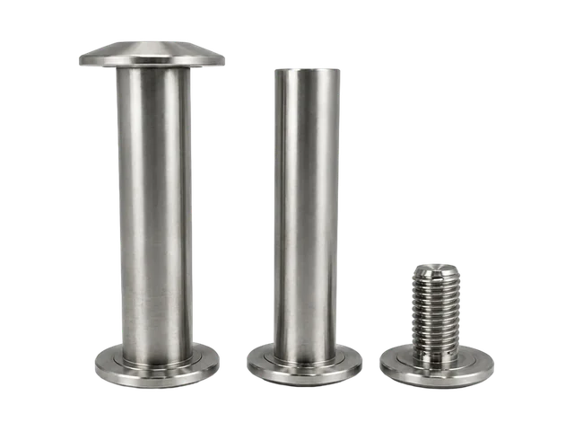
Configuration 06 pivot shafts and separate threaded component
Existing PremFixer configuration 06 photograph. Shafts and a separate threaded component illustrate a hardware group; the approved assembly drawing defines the mating relationships.
Original PS-P04 shaft drawing with shoulder, thread and flat featuresPS-P04 shaft drawing

Keep the geometry and the joint connected

This original shaft drawing is a separate technical reference for shoulders, threads and flats. It is not the drawing for the photographed set above. Cross-reference each purchased part to its own approved drawing and mating assembly.

Review precision turning & turn-mill manufacturing →

04 / Rear frame interface

Dropout & Derailleur Hanger Fixing Hardware

Define the seat, frame-end thickness, thread engagement, axle-to-hanger position and tool access against the OEM revision. Conventional hanger assemblies, UDH and Full Mount have different component requirements; a familiar-looking bolt does not establish compatibility.

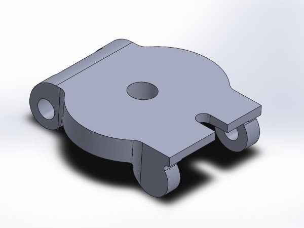
PS-K12 dropout and hanger technical rendering with an open axle slot
PS-K12 technical rendering · source 614-804-001R+. Open axle-slot geometry; no UDH, Full Mount or thru-axle fit is claimed.
Original PS-K12 drawing with separate dropout and hanger viewsPS-K12 dropout drawing
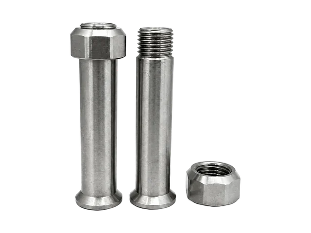
PS-A02 countersunk hanger bolt references
PS-A02 · Countersunk hanger bolt reference
PS-A03 double-through hanger nut references
PS-A03 · Double-through hanger nut reference

Specify the mating parts separately

These are independent catalog references, not a verified bolt-and-nut pair. Require the same approved thread interface and clamp stack before quoting a matched set.

Full Mount attaches directly at a compatible frame interface instead of using the UDH hanger. Use the current frame and drivetrain documents, including SRAM's architecture guide, for the required arrangement.

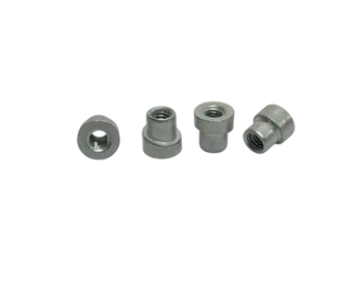
PS-A04 chainring nut references with internal threads
PS-A04 chainring nut photograph. Mating bolts are not shown; this is a nut reference, not a complete bolt-and-nut set.

05 / Confirm the assembly purchasing scope

Chainring Bolts, Frame Fasteners & Assembly Hardware

Chainring hardware belongs in the frame program only when the agreed BOM assigns it to this order. A crankset or drivetrain supplier may already supply these parts.

The specific crank and chainring arrangement determines bolt and nut geometry, engagement, clamped thickness, material and quantity. Crank fixing bolts, direct-mount systems and lockrings are separate requirements.

Review Assembly Hardware Scope
PS-M01 cable-guide rendering with multiple routing positions
PS-M01 cable-guide technical rendering. The guide and its fixing hardware require separate material and supply definitions.

Account for the smaller mounting points

For e-bike programs, identify the external motor or battery mounting version. Cells, battery electrical design and drive-unit internals are outside this mechanical hardware scope.

06 / Procurement decisions

Frame Alloy, Joining Route & Finished Hardware

An aluminum frame does not require every fastener to be aluminum. Select materials per component, then review joining, corrosion exposure and the final functional surfaces.

Frame / component conditionReview firstInclude in the RFQ
6061 or 7005 frameBoss base metal, welding procedure and required post-weld conditionFrame alloy and approved fabrication procedure
Aluminum weld-on fittingAlloy compatibility, joint design and finishing sequencePart alloy / condition, joining specification and delivery stage
Steel or stainless insertMechanical retention and corrosion protectionInstallation method, hole and wall conditions, load criteria
7075 / 6061 machined hardwarePart temper, loading, contact surfaces and fitApproved part drawing, material condition and finish
Painted or anodized frameFinished holes, threads, mating faces and protectionReceiving condition, masking and finished dimensions

Welding changes the material condition.Do not apply unwelded 6061-T6 properties to a welded joint without qualification. The frame maker defines the heat-treatment route and acceptance requirements for its 6061 or 7005 structure. 7075 is a possible machined-part material, not a default weld-on boss choice. ESAB explains alloy and welding considerations.

Review the completed interface.Thin-wall insert retention, coating allowance, galvanic exposure and assembly load need project-specific decisions. Thread size or alloy name alone cannot determine installation torque or fatigue life. Explore the materials guide and the existing aluminum-frame systems overview; approved project documents govern selection.

07 / One procurement register, separate responsibilities

A Frame Hardware BOM Across Manufacturing Stages

Keep each drawing number, revision and supply owner visible. Separate frame-factory items, brand-specified components, drivetrain-supplied parts and the components PremFixer is asked to manufacture.

  1. Frame drawing
  2. Stage / interface
  3. Part no. + rev.
  4. Material & route
  5. Per-frame qty.
  6. Quotation & supply group
Model / Platform
Frame Revision · BOM Revision · Drawing Revision
Installation condition
Finish Stage · receiving state · installation owner
Quantity basis
Qty per Frame · Qty per Bike · Requested Quantity · Unit (piece / pair / set)
Supply grouping
Packing Group · Delivery Site · included and reference-only items

Illustrative structure only — not a real customer order or an approved specification. Scroll horizontally on small screens to compare all fields.

Example Part No.Stage / LocationComponentMaterial / RouteDrawing Rev.Qty per FrameSupply Responsibility
EX-F01Frame fabricationWeld-on aluminum bossApproved aluminum joining routeAPer approved BOMPart manufacture; installation by frame plant
EX-F02Frame interfaceThreaded mechanical insertDrawing-defined post-fabrication fixingBPer approved BOMPart manufacture
EX-P01Assembly / pivotPivot axleApproved part drawingAPer approved BOMPart manufacture
EX-P02Assembly / pivotMating sleeveApproved part drawingBPer approved BOMPart manufacture
EX-H01Rear dropoutHanger fixing boltApproved part drawingAPer approved BOMPart manufacture
EX-H02Rear dropoutMating threaded pieceDrawing-specificAPer approved BOMPart manufacture if included
EX-C01DrivetrainChainring bolt or nutCrank / chainring-approved drawingCPer approved BOMConfirm supplier responsibility
REF-B01AssemblyBearing or sealOEM reference—Per approved BOMReference only unless agreed

Count parts against the actual configuration.Each drawing keeps its own quantity. List samples and spares separately, and distinguish pieces, pairs and sets. Different frame sizes or model revisions may change only selected lines; do not assume a fixed pairing ratio.

Quote the agreed manufacturing scope.Identify customer-supplied and reference-only items before sampling. A kit label does not include every visible bearing, seal, crank component or accessory. Compare this frame-stage register with the broader Bicycle OEM program or MTB assembly hardware kits.

Send a Frame Hardware BOM

08 / Component manufacturing and acceptance

Manufacturing Behind Frame Hardware

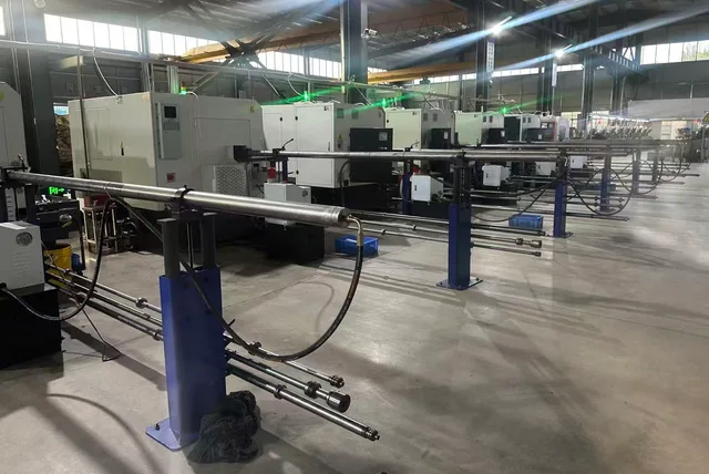
The part drawing determines the manufacturing route. CNC work, forming, threading and tooling are selected operations; every part does not pass through one identical process chain.

CNC lathe production line with bar-feeding equipment in the PremFixer workshop
Existing PremFixer workshop photograph: CNC lathes and bar-feeding equipment. View turning and turn-mill capabilities.
CNC Turning
Diameters, shoulders, bores and end faces for axles, sleeves and mounting pieces; the PS-P04 drawing above provides a geometry reference.
Turn-Mill Machining
Turned features combined with flats, slots or cross-holes. Review feature orientation and tool access against the part drawing.
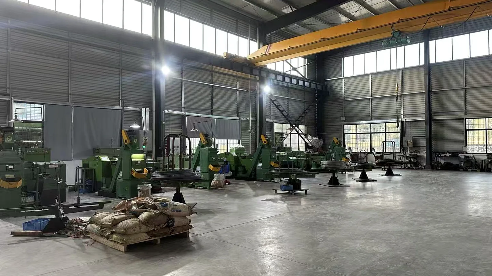
Cold Heading
Formed heads and blanks for suitable fastener geometry and materials, with the production route agreed per item.
Thread Rolling
External threads on suitable blanks. The visible threaded hardware is a shape reference, not proof that every shown thread was rolled.
Tool / Die Development
Part-specific forming and manufacturing tools support the agreed shape and repeat production; tooling scope is confirmed with the order.
Existing PremFixer cold-heading machine and wire coils
Existing cold-heading equipment and wire coils. View manufacturing and tooling scope.

Inspect the features that control assembly

Confirm drawing revision and material, internal threads and anti-rotation features, fitting contact faces, shaft / sleeve dimensions and critical dimensions after finishing. Agree inspection records and packing labels with the order.

Review quality control →

Keep component and frame approval distinct

PremFixer supplies the agreed manufactured parts. The responsible frame plant or brand approves structural changes, weld quality, frame fabrication and bicycle-level functional validation. Partner operations and documentation are defined in the quotation.

Review multi-part manufacturing responsibility →
Original ISO 9001 certificate for Guangdong Pinshang Hardware Products Co., Ltd.Original ISO 9001 certificate ↗

ISO 9001:2015 Quality Management

Guangdong Pinshang Hardware Products Co., Ltd.
Bureau Veritas Certification · F02326Q00193R002 / CN059955
28 April 2026–27 April 2029, subject to continued satisfactory operation and monitoring.

Certified scope: Production of hardware screws and nuts. This management-system certificate is not approval of every frame fitting, welded structure or complete bicycle.

Read the certification record →

09 / From initial list to repeat order

From Frame Drawing to Approved Hardware Supply

  1. 01 / Initial RequestShare available frame CAD, part drawings, samples or a preliminary BOM. An incomplete list is enough to begin the discussion.
  2. 02 / Frame Interface ReviewIdentify the component scope by material, joining method and frame production stage.
  3. 03 / Itemized RFQQuote each drawing, material condition, finish, quantity and packing requirement separately.
  4. 04 / Sample & Assembly EvaluationComplete agreed part inspections; the customer evaluates fit and the assembly configuration.
  5. 05 / Approved Production ReleaseUse the authorized drawings and BOM. Design changes need approval from the responsible design owner.
  6. 06 / Packing, Delivery & RepeatGroup parts by frame or bicycle workstation, identify revisions and control changes on repeat orders.

Manufacturing feedback helps resolve part-production questions. It does not authorize changes to the frame's load-bearing design.

10 / Engineering and sourcing questions

Aluminum Frame Hardware Questions from OEM Teams

What hardware can PremFixer supply for an aluminum bicycle frame OEM project?

An agreed project can include drawing-defined weld-on frame fittings, threaded mounting components, pivot bolts, axles, sleeves, spacers, hanger fixing parts and other bicycle assembly fasteners. The frame and model BOM determine which items are supplied. A component visible in an assembly drawing is not automatically included in the quotation or manufactured by PremFixer.

What is the difference between a weld-on frame boss and a threaded insert?

A weld-on boss is designed for integration using the frame builder’s approved joining process, with its alloy and geometry matched to the frame. A threaded insert may use a separate mechanically retained, pressed, riveted or otherwise approved installation method. The names can overlap in a product catalog, so the material and installation method must be specified in the project drawing.

Can stainless steel weld nuts be TIG-welded directly to a 6061 aluminum frame?

Conventional TIG fusion welding is not an interchangeable joining method for steel and aluminum. Direct joints can form brittle intermetallic compounds and require specialized engineering. A stainless or steel threaded insert for an aluminum frame should therefore have its joining or retention method reviewed separately. We manufacture the drawing-defined component; the frame maker approves and validates its installation process.

Can you provide aluminum weld-on bosses for 6061 or 7005 frames?

Aluminum weld-on fittings can be discussed against the frame drawing, base alloy, joint design and approved fabrication process. The frame manufacturer should define the joining procedure and any required post-weld treatment. We review the part geometry, material and machining requirements as an OEM component order; this does not mean that PremFixer welds or validates the complete frame.

Are all PS-E weld nuts intended for the same installation method?

No. A product family label is not a substitute for a production specification. Similar-looking bosses or inserts can use different materials and installation methods depending on the frame and the intended joining stage. Please identify the exact part drawing, frame material and required retention or joining process before selecting a reference from the PS-E library.

Can one frame program use aluminum, stainless steel and other fastener materials?

Yes. Frame material and fastener material are separate design decisions. A project may specify different grades for weld-on aluminum fittings, CNC-turned axles, threaded inserts or other mounting parts. Each BOM line should state its approved grade, condition, finish and functional surfaces. Different metals in contact also require a project-specific corrosion and assembly review.

Can PremFixer manufacture matched pivot bolts, axles and sleeves for an alloy frame?

Yes. Our manufacturing range includes custom fasteners and precision turned parts such as pivot axles, shoulders, sleeves, spacers and mating locking components. A hardware set must be defined by the approved joint or assembly drawing. Bearing-contact dimensions, axial stack, threads and required per-frame quantities are established for each location rather than inferred from a reference product photo.

Can you provide hanger fixing bolts and nuts for aluminum frames?

We can manufacture drawing-defined bolts, nuts and threaded parts for approved hanger or dropout assemblies. The frame-end geometry, seat, clamp thickness and retention method must be known. Traditional hangers, SRAM UDH and Full Mount interfaces are not automatically interchangeable, so the drawing and the drivetrain architecture must define what is required.

Are chainring bolt-and-nut sets included with an aluminum frame kit?

Only if the agreed project BOM includes them. Chainring hardware may be specified and purchased with a crankset or another drivetrain assembly rather than with the bare frame. The required bolt, mating nut or barrel and quantities depend on that specific mounting arrangement. Direct-mount or lockring interfaces and crank fixing bolts are separate requirements.

At which production stage should threaded inserts be installed?

The installation stage depends on the part design and the frame maker’s manufacturing plan. Weld-on aluminum fittings, mechanically retained inserts and after-paint mounting fasteners can have different sequencing and finished-surface requirements. The frame factory should identify the installation stage, the condition of the frame and any necessary masking, protection or inspection in its approved procedure.

Can you supply parts for both hardtail and full-suspension aluminum frames?

Yes, within the agreed drawing and manufacturing scope. A hardtail normally does not require rear-suspension pivot hardware, while a full-suspension design may include multiple pivot and shock mounting assemblies. Bottle bosses, hanger fixing and other frame hardware also vary by model. We organize the quotation by actual frame configuration and approved BOM rather than one universal kit.

What do you need to quote a new frame hardware program?

You can start with frame drawings, a preliminary hardware list, sample photos or a draft BOM. Include the frame alloy, model or platform, estimated quantities and the manufacturing or assembly stage for the requested components where known. The detailed drawing revision, material and finish specifications, installation responsibility and acceptance criteria are confirmed before release to production.

Can you pack hardware by frame model or assembly workstation?

Packing can be arranged by part number, subassembly, frame model or workstation as agreed for the order. The item list should define the included components, quantities, drawing revisions and labels. A model-specific hardware supply program does not automatically mean a sealed retail pack for every bicycle. Reference-only or customer-supplied items remain excluded unless explicitly quoted.

Does ISO 9001 certification mean every frame mounting component is approved for use?

No. ISO 9001 certifies the quality management system within the scope stated on the certificate; it does not establish universal compatibility, structural weld approval or vehicle-level safety validation. The frame manufacturer and design owner define and approve the application. Individual parts are manufactured and inspected according to the agreed drawings, materials and project acceptance requirements.

Start with the information you have

Send Your Aluminum Frame Hardware Drawings or BOM

Share your frame or model reference, the drawings or BOM you currently have, and the quantities required for your project. Identify which fittings are installed during frame fabrication and which fasteners are supplied for final assembly. We will clarify the part-by-part manufacturing and supply scope with you.

Request an Aluminum Frame Hardware QuoteExplore Existing Frame Inserts →

Start with contact details and a brief project description. Drawings, frame alloy, installation stage and BOM details can follow as they become available.

Original document

Loading original document…

Open original in a new tab ↗