
E-MTB OEM HARDWARE PROGRAMS
One-Stop e-MTB Fastener & Frame Hardware Supply
PremFixer manufactures custom fasteners and precision turned components for electric mountain bike OEM projects. Combine pivot kits, hanger fixing parts and chainring fasteners with agreed motor-interface, battery-mount and frame hardware in one drawing- and BOM-led supply program. Your model, system configuration and approved part list define the supplied scope.
Separate parts. One defined supply scope.
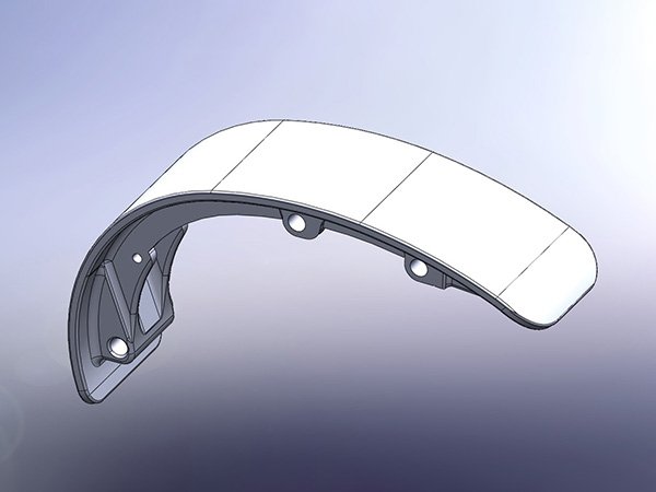 PS-R02 technical renderReview the drive-unit interface
Pivot Kits · Hanger Fixings · Chainring Hardware · Motor & Battery Interfaces
Hardware Across the e-MTB Assembly
Mark the interfaces in your project, then identify the parts to source. This scope map is a purchasing reference; the approved assembly defines geometry and fit.
- Suspension & linkageBolts, axles, sleeves, spacers and nuts for the specified joints.
- Hanger & dropoutFixing bolts and threaded mating parts for the rear-frame architecture.
- Chainring & crankIdentify the chainring, spider or direct-mount interface.
- Drive-unit to frameSpecified fixings, locating sleeves and interface parts.
- Battery mechanical mountProject-defined bracket, retention and latch-base hardware.
- Covers & guardsCover and skid-plate attachments with defined tool access.
- Cable & sensor routingGuides and mechanical bracket attachments clear of service paths.
- Other frame hardwareAgreed shock, axle, brake, seat, bottle and insert line items.
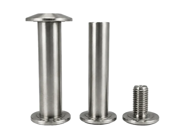
e-MTB Pivot Kits & Matched Suspension Hardware
We manufacture the agreed bolts, axles, sleeves, spacers and retaining parts by suspension position, part number and revision. Full-suspension joints need their own mating definitions; a hardtail does not acquire rear-suspension hardware simply because it is electric.
Review shoulder length, bearing and spacer contact faces, mating threads, installation side and tool clearance around the drive unit or guard. Motor output torque is not the fastener installation torque. The approved joint specification defines tightening and locking requirements.
Discuss an e-MTB Pivot KitDimensions belong to the individual part.
Match the released assembly before pairing.
 PS-P04 shaft drawing
 PS-H03 spacer drawing
Derailleur Hanger Fixing Bolt & Nut Sets
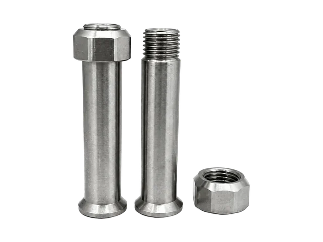
Drawing-defined bolts and mating nuts or threaded sleeves secure the specified hanger to the frame. Hanger retention is separate from the derailleur’s mounting bolt.

Individual product photograph

Individual product photograph
Define the retention arrangement
Specify head seats, clamped thickness, engagement, thread direction, anti-rotation features and tool access. These two catalogue references are not a verified mating pair.
Conventional hangers, UDH and hangerless Full Mount use different mounting arrangements. Confirm the actual architecture and any required system-provider approval before substituting hardware.
SRAM architecture reference ↗Send the Hanger Interface DrawingChainring Bolt & Nut Sets for the Specified Drive Interface
Quote the fastening arrangement shown on the approved chainring and crank assembly. Hole pattern, seats, clamped thickness, usable thread engagement and two-sided tool access define a bolt-and-nut set.
- Bolt & mating nut
- Include the chainring, spider, guard and any spacer in the actual stack.
- Direct mount / lockring
- A separate interface requiring the relevant system drawing.
- Crank fixing
- A separate line item with its own seating and retention requirements.
No universal hole count, thread, chainline or tightening value is assumed.
Review Chainring Mounting Hardware
Nut only. A mating bolt requires its own drawing; this reference is not a drive-unit lockring.
Defined by the mechanical interface
Drive-Unit Mounting & Surrounding Frame Hardware
Provide the complete drive-unit model and version with the frame-side mounting drawing. Platform names alone do not establish compatibility or permission to replace supplier-specified components.
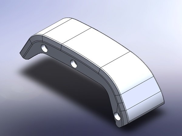
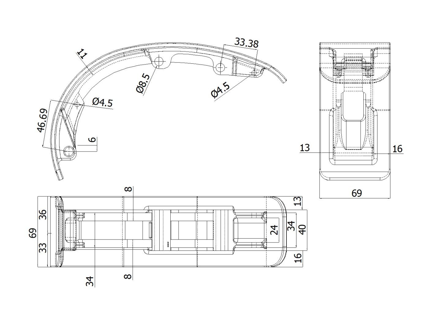 PS-R02 original cover drawing
Review four separate functions
- Structural fixing
- Approved bolts, mounting faces and entry directions.
- Locating & spacing
- Sleeves, inserts and spacers against mating materials.
- Covers & skid plates
- Attachment points and removal access.
- Routing brackets
- Clearance for cables, adjacent parts and tools.
Identify hardware already included with the drive unit. Agree manufacturing, sourcing and approval responsibility before quotation.
Share the Drive-Unit Mounting InterfaceBattery Retention & Mounting Hardware
Discuss mechanical fixings, sleeves, spacers and attachment parts against the actual battery-mount design. Retention hardware and cover fasteners have separate jobs; a cover does not automatically retain the battery.
Identify the mount version, fixed or removable arrangement, insertion direction, contacts, retention method and cable clearance. Battery capacity in Wh and a marketing name do not define the mechanical fit.
System-specified locks and retention assemblies remain subject to their supplier requirements. This scope concerns mechanical hardware, separate from cells, BMS, controllers and complete battery packs.
Complete the Agreed Frame Hardware Scope
Add cover, guard, cable-guide, sensor-bracket and charge-port-cover fixings as separate mechanical line items. Review access, inserts, finishes and removal paths without inferring electrical compatibility.
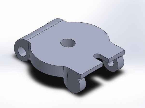
Shock mounting, axle-related retainers, brake attachments, seat hardware and bottle bosses can be reviewed where the project calls for them. PS-E01 illustrates a frame insert, not a battery-retention product. PS-M01 is a routing geometry reference; material and manufacturing responsibility need confirmation.
Explore custom fasteners →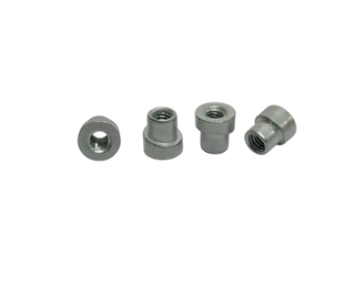
From configuration to quotation
One e-MTB Platform, One Itemised Hardware Scope
A model name is a starting point. Connect each build configuration to its released drawings, quantities and purchasing responsibilities.
- Frame & build
- Model / frame revision / suspension configuration / build quantity
- System interfaces
- Drive-unit model & version / battery mount version / drivetrain interface / hanger architecture
- Controlled release
- BOM revision / approved part revisions / supply responsibility
Illustrative Project A
Defined frame and system-interface release.
Changed drive unit or battery mount: review affected line items.
Shared Approved Parts require an explicit reuse decision. Configuration-Specific Parts remain tied to their own release.
Illustrative BOM format — not a customer order or a manufacturing specification.
| Example / assembly | Item / revision | Qty per bike | Mating reference | Supply decision |
|---|---|---|---|---|
| EX-P01 / Pivot | Axle / A | Approved BOM | EX-P02 | Manufacture |
| EX-P02 / Pivot | Locking component / A | Approved BOM | EX-P01 | Manufacture |
| EX-H01 / Hanger | Fixing bolt / B | Approved BOM | EX-H02 | Manufacture |
| EX-H02 / Hanger | Threaded mating part / B | Approved BOM | EX-H01 | Manufacture |
| EX-C01 / Chainring | Bolt / A | Approved BOM | EX-C02 | Manufacture if specified |
| EX-C02 / Chainring | Mating nut / A | Approved BOM | EX-C01 | Manufacture if specified |
| EX-M01 / Drive-unit interface | Specified fixing / per release | Approved BOM | Mounting drawing | Responsibility to confirm |
| EX-M02 / Frame interface | Locating sleeve / per release | Approved BOM | Mounting drawing | Drawing-led scope |
| EX-B01 / Battery mount | Mechanical fixing / per release | Approved BOM | Battery mount drawing | Drawing-led scope |
| REF-S01 / System package | Supplier-specified item / supplier reference | Reference only | Supplier assembly | Not included unless agreed |
Additional fields for the working BOM
Material and condition, finish, piece/pair/set/kit unit, total quantity, sample quantity, separate spares, acceptance criteria and packing group.
Count parts once
For each part, sum approved per-bike quantities × build quantities across configurations, then add agreed spares separately. Distinguish pieces, pairs and kits; do not add a kit total to its component totals. Samples have their own quantity.
Confirm the quote scope
Exclude already-supplied hardware unless agreed otherwise. Identify tooling, finish, inspection, packing and delivery requirements. One project coordinator does not replace system-provider approval.
Manufacturing & Quality Against the Released Drawing
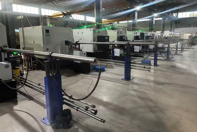
Choose the process for each geometry, material and quantity. A multi-part program can combine different manufacturing routes.
Turned and formed parts
CNC turning supports shafts, sleeves, shoulders and bores; turn-mill operations add suitable cross-holes, flats and slots. Heading and tooling suit appropriate formed parts, with thread rolling for suitable external threads.

Material and finish by part
Discuss drawing-specified steels, stainless grades such as 304/316, aluminium such as 6061/7075, or titanium where appropriate. Grade, condition, treatment and finished acceptance are separate requirements. Locking patches, lubrication and washers follow the approved joint specification.
Inspect the mating features
Define finished shoulder lengths, spacer faces, threads, seating surfaces, post-finish dimensions and cross-hole burr control. Agree inspection records and part/batch traceability against the released requirements.
 Open original certificate
Supplier qualification, with a defined scope
The ISO 9001:2015 certificate names Guangdong Pinshang Hardware Products Co., Ltd. and covers production of hardware screws and nuts. It concerns the quality management system, not certification of every kit, battery system or complete bicycle.
Certificate details →From First Files to Repeat Orders
Start with the information available. Manufacturing begins against the authorised drawings, BOM and agreed acceptance requirements.
- Drawings / BOMIdentify the configuration and requested parts.
- Itemised scope & quoteAgree responsibilities, quantities and requirements.
- Approved releaseConfirm drawings and BOM revisions.
- Samples & agreed checksIdentify differences from production requirements.
- Production & inspectionManufacture and check the agreed finished parts.
- Packing & repeat ordersLink labels to part, revision, quantity and batch.
Group by part number, subassembly, station or approved model kit. Retail bags are not assumed. DFM suggestions require design approval; a new revision applies only to the approved configurations. Review multi-part manufacturing →
e-MTB Hardware Sourcing Questions
What can be included in an e-MTB hardware supply program?
An agreed program can combine pivot hardware, hanger fixing parts, chainring fasteners and selected frame, motor-interface or battery-mount components. Each supplied item is identified in the project BOM. The list also distinguishes parts already provided with the drive unit, battery system, frame or crankset so the quotation does not duplicate another supplier’s scope.
How is an e-MTB hardware program different from an MTB fastener kit?
The e-MTB project also needs the drive-unit and battery-mount configuration to be identified. Those interfaces can introduce additional fixing parts, covers, routing constraints and supplier-specified components. Existing frame and drivetrain hardware still follows its own drawings. An electric drivetrain does not make one kit or one tightening specification suitable for every platform.
Can you manufacture matched pivot bolts, axles, sleeves and nuts?
Yes. Our manufacturing scope includes drawing-defined fasteners and precision turned components that can be supplied together for approved pivot assemblies. Identify the mating parts, locations, drawing revisions and quantity per bike. Existing product photographs provide geometry references; the contents and finished requirements of a new kit come from the customer’s released drawings and BOM.
Can you provide derailleur hanger fixing bolt-and-nut sets?
We manufacture drawing-defined bolts, nuts and threaded mating parts for the specified fixing arrangement. Share the hanger and frame interface, clamped thickness, seating geometry and thread requirements. The derailleur mounting architecture must be identified separately; a general hanger reference does not establish that a part fits a UDH interface or a hangerless mounting arrangement.
Do all e-MTB chainrings use a bolt-and-nut set?
No. The mounting arrangement depends on the crank, chainring and drive system. Some projects specify a bolt-and-nut connection, while others use a direct-mount or lockring interface. Crank fixing hardware is another separate requirement. Send the actual interface drawing or component reference so the quotation covers the correct parts rather than assuming one universal chainring fastening method.
Can motor-platform names confirm compatibility on their own?
No. Provide the drive-unit model and version together with the frame-side mounting drawing and any supplier-defined requirements. A platform name or old product label is not a complete mechanical specification. We use those details to identify the requested manufacturing scope, mating interfaces and items that must remain supplied or approved by the system provider.
What battery-related hardware can be discussed?
The discussion can cover drawing-defined mechanical mounting and attachment parts, such as bracket fixings, sleeves, retaining interfaces or cover fasteners within an agreed scope. This is separate from the battery cells, electronics and complete battery pack. Dedicated parts and acceptance requirements need the actual mounting design; a generic spacer photograph does not establish a complete battery-retention product.
Are all components in the assembly drawing included in the quote?
No. The quotation identifies the accepted supply scope item by item. A component may be manufactured by PremFixer, sourced by agreement, supplied by the customer or system provider, or shown only as a mating reference. This distinction is especially important where mounting hardware is already included with a drive unit, frame, battery mount or crankset.
Can one BOM contain different materials and finishes?
Yes. Specify the material grade, condition and finish for each part, together with the relevant finished dimensions and acceptance requirements. Different assembly locations may need different specifications. A material change or coating change is not automatically an interchangeable substitution, and the e-MTB label alone does not determine a universal material or bolt-tightening value.
Do you support prototypes and later production orders?
Yes. Prototype, initial production and repeat-order quantities can be discussed for the approved manufacturing scope. State the intended stage and quantities, including whether samples need the production finish. Tooling, timing and inspection requirements depend on the project. Any change between sample and production requirements should be identified and approved before release.
How should different motor or battery configurations be handled?
Give each configuration an identifiable BOM and the applicable drawing revisions. Mark which parts are approved to be shared and which are configuration-specific. When a drive-unit version, battery mount or drivetrain interface changes, review the affected line items rather than assuming the entire previous kit remains interchangeable. Repeat orders should reference the released configuration, not only the bicycle’s marketing name.
Can hardware be grouped by assembly station or bicycle model?
Yes, grouping requirements can be defined for the order. Parts may be packed by part number, subassembly, production station or an approved model-specific kit. Agree the quantities, revisions, identification and packaging before production. One-stop supply does not automatically mean retail packaging or one bag per bicycle, and additional service spares are listed separately.
Does ISO 9001 certify every e-MTB kit or the complete bicycle?
No. The available certificate concerns the quality management system within its stated organizational scope. It is supplier-qualification information, not a universal compatibility or vehicle-performance approval. The project specifies the actual part acceptance requirements, agreed inspection records and any additional validation responsibilities. Use the original certificate page when reviewing the certification details.
What should I send to start an e-MTB hardware quotation?
Send the drawings, preliminary BOM or sample information you already have, plus the project stage and quantities. Identify the frame model, drive-unit version and battery-mount arrangement where known, and mark which items you need supplied. Initial information can be incomplete; the production scope, approved revisions and acceptance requirements are clarified before manufacturing release.
Your next hardware program
Send Your e-MTB Hardware Drawings or BOM
Share your model or project reference, the drawings or part list you have, and the quantities you need. Identify the frame, drive-unit and battery-mount configuration where known, and mark the hardware you want us to supply. We will define the manufacturing and quotation scope around your project.
Request an e-MTB Hardware Quote