
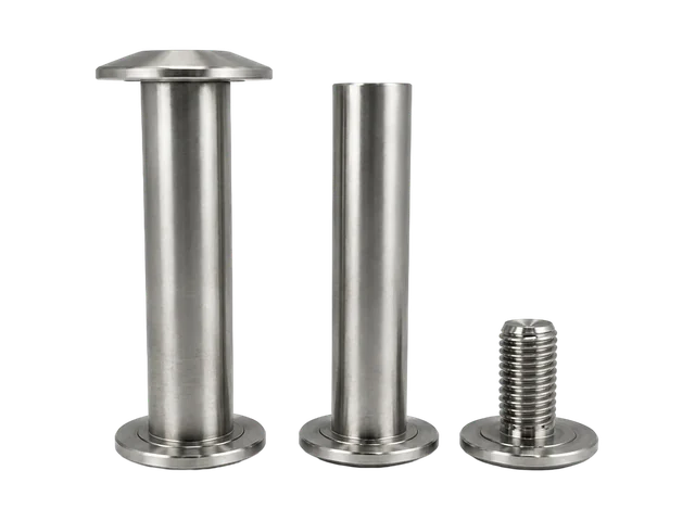
Existing PremFixer product reference
Flanged sleeve and locking screw reference
Existing bicycle hardware shown to explain separate component identities and contact surfaces.
View original record →Manufacturing / Multi-part projects
Bring the bolts, shafts, sleeves, nuts and spacers in your assembly into one drawing-led manufacturing review. PremFixer reviews each part, its mating interfaces and the required quantities to define the manufacturing and supply scope for your project. Start with an itemised BOM and the drawings that establish how the parts fit together.
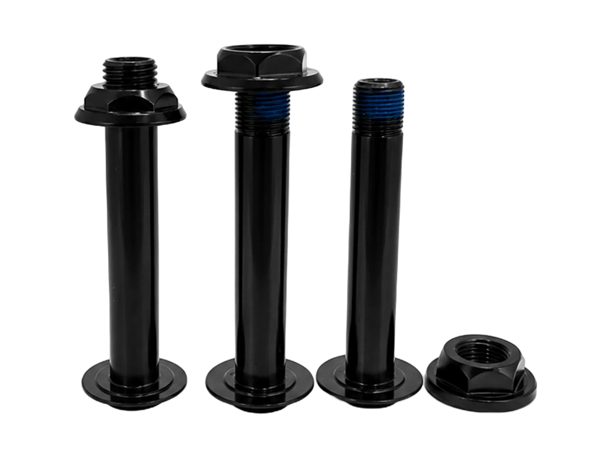
A shared assembly can contain a turned shaft, a flanged sleeve, a threaded locking part and a separate spacer. Each item still needs a drawing identity, quantity and acceptance requirement. Reviewing the group together makes relationships visible: a change to the sleeve length may also affect the shoulder position, exposed thread or assembly sequence.
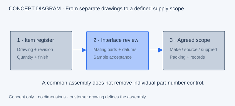
The first output is an agreed scope for each line item. Identify which items PremFixer is asked to manufacture, which purchased components need separate sourcing confirmation and which mating parts the customer will supply. Bearings and other catalogue components can remain reference items while the custom hardware around them is reviewed.
These existing bicycle hardware groups illustrate flanges, shoulders, threaded connections and drive features. Use their geometry to explain the new assembly; retain your own part numbers and application requirements.
Existing bicycle hardware shown to explain separate component identities and contact surfaces.
View original record →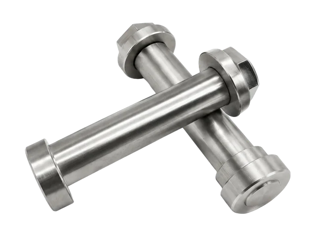
Original bicycle components illustrate shoulder and flange relationships for a separate project review.
View original record →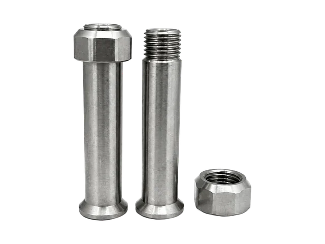
A reference for drive access and paired threading, retaining its original bicycle application.
View original record →Give every requested item its own row. A single description such as “pivot kit” leaves the number of sleeves, locking pieces and spares open to interpretation. A useful BOM connects the approved drawing revision to the required quantity per assembly and the total order quantity. State whether samples use the same finish and packing as production.
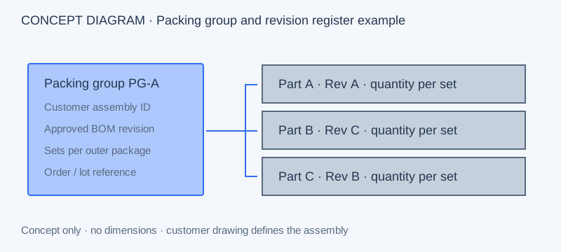
| Customer part number | Revision | Function | Mating part | Material / finish | Qty per assembly | Acceptance | Packing group |
|---|---|---|---|---|---|---|---|
| Part A | A | Shouldered shaft | Part B | Customer drawing | 1 | Fit diameter and shoulder | PG-A |
| Part B | C | Flanged sleeve | Parts A / C | Customer drawing | 1 | Bore and contact faces | PG-A |
| Part C | B | Locking fastener | Part A or B, as designed | Customer drawing | As defined | Thread and seating face | PG-A |
Add an assembly reference and mark customer-supplied items in the same register. When several configurations share a common shaft but use different sleeves, show the configuration-to-item relationship explicitly. This gives purchasing a comparable scope and keeps shared components distinct from configuration-specific parts.
The assembly drawing defines the relationship between dimensions on separate parts. Identify the shoulder that locates the sleeve, the faces that receive clamp load and the threaded connection that retains the stack. Include the intended installation order and the tool envelope, particularly where a nut or recessed drive becomes inaccessible after another component is installed.
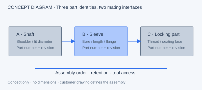
Connect the BOM to the existing custom fastener, precision component and shaft and axle families. The CNC turning review covers drawing-led rotational geometry; secondary features and surface treatments require their own review against the actual component.
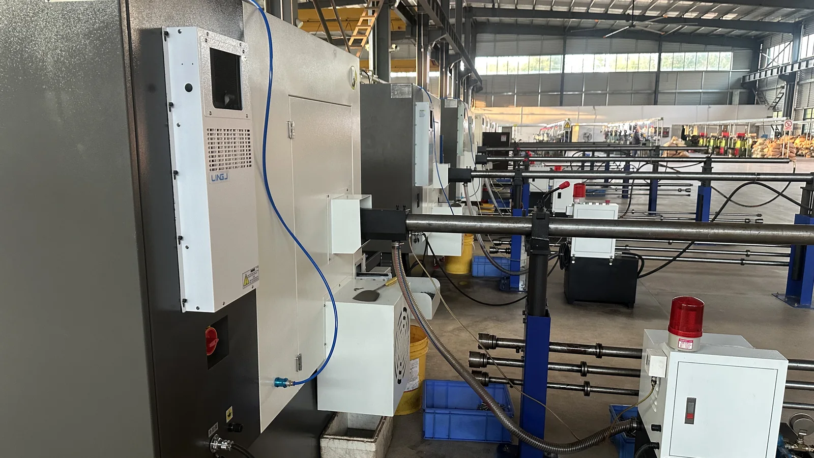
State the proposed material and finished condition per item. Different members can need different treatments, making the mating condition more useful than a single finish note for the entire set. Record confirmed in-house operations and any agreed partner operations in the quotation scope. Discuss alternatives through the materials guide before approving a change to the drawing.
A sample matrix should distinguish individual dimensional checks from paired assembly checks. List the item, revision, sample quantity, finish condition and mating reference to be used. If the customer supplies the mating part, identify it before sampling; an unspecified substitute can change the meaning of a fit result.
Agree the inspection records required for each critical feature and how a result connects to the relevant item or order. Traceability depth, material documentation and sample retention are project requirements to confirm in the quotation. Customer approval of the set should reference the accepted configuration and the conditions used to assess it.
For grouped supply, define the packing group, every included item and the quantity per group. Specify whether similar lengths need separate identification, whether a customer-supplied component is excluded and which fields appear on the label. Confirm the available packing arrangement as part of the manufacturing quotation.
A service or replenishment request can use this same register: customer Kit ID, approved BOM, revisions and quantities. The customer defines intended compatibility. Standalone service-kit fulfilment requires a separately agreed supply scope; this review establishes the component and packing requirements first.
For repeat orders, send the current BOM together with a list of changed drawings. Identify affected mating parts and the required treatment of previously approved samples or remaining stock. A familiar assembly name should always resolve to a specific approved revision set.
The full-suspension system shows pivot-related hardware and a frame BOM context. The folding-bike solution covers hinge and locking relationships, while the hardtail program provides a separate frame assembly route. These retain their specific bicycle scope; this service page organises the shared multi-part manufacturing review.
Send the current item register and assembly drawing together. Highlight open material, finish or sourcing decisions so the quotation can identify assumptions alongside the proposed scope.
Yes. Send the itemised BOM with the drawings and an assembly reference. The review identifies the requested custom components, mating interfaces and any purchased or customer-supplied items. Manufacturing and supply responsibility is then confirmed line by line.
Use customer part numbers in both the BOM and the assembly drawing. Mark the relevant contact face, fit or thread and name the mating revision. Include reference-only parts even when they are outside the requested supply scope.
They can be reviewed separately by item. Specify the proposed condition and which dimensions apply after treatment. Any material combination, surface requirement or changed fit should be assessed against the customer’s approved assembly requirements.
Agree the drawing revisions, sample quantities, finish condition, mating references and acceptance checks. Distinguish measurements on individual components from customer assessment of the assembled group. Record open decisions before sample manufacture.
Provide the current approved BOM and flag changed drawings. Link a change to every affected mating item, label and packing group. Confirm whether earlier samples remain applicable before treating a repeat order as the same approved configuration.