
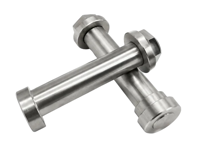
Existing PremFixer product reference
Flanged paired pivot reference
Original bicycle components illustrate shoulder and flange relationships for a separate project review.
View original record →Project application / Bracket mounting
Custom motorcycle bracket mounting hardware starts with the attachment drawing and the surfaces it connects. PremFixer reviews bolts, spacers, sleeves and locating parts for customer-defined accessory or bracket projects. Supply the mounting distance, mating holes, tool access and quantities so the proposed components can be assessed against the actual installation and sample acceptance requirements.
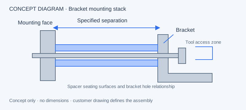
Show the two surfaces that the hardware connects and the space between them. A spacer may establish the bracket position, while a shoulder or sleeve locates in a hole and a separate fastener provides retention. Identify these roles at every attachment point, including any points that use a different stack of parts.
An accessory drawing is most useful alongside the mating mounting surface. Include nearby geometry that affects seating, insertion and tool access. If a component is customer-supplied or outside the requested quotation, retain it as a clearly identified reference in the assembly view.
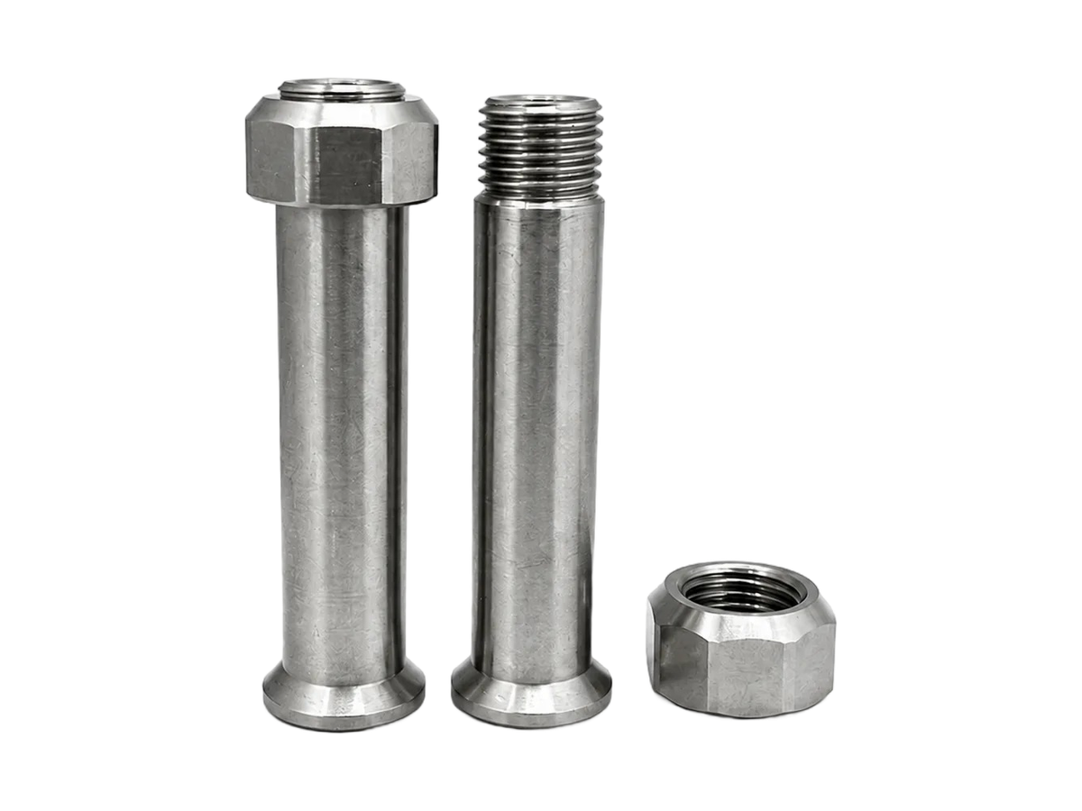
The photographs show existing bicycle hardware; the PS-P02 image is a technical rendering. Flanges, external threads and stepped shaft features provide manufacturing references for a separate motorcycle project. Project drawings and customer acceptance establish the new use.
Original bicycle components illustrate shoulder and flange relationships for a separate project review.
View original record →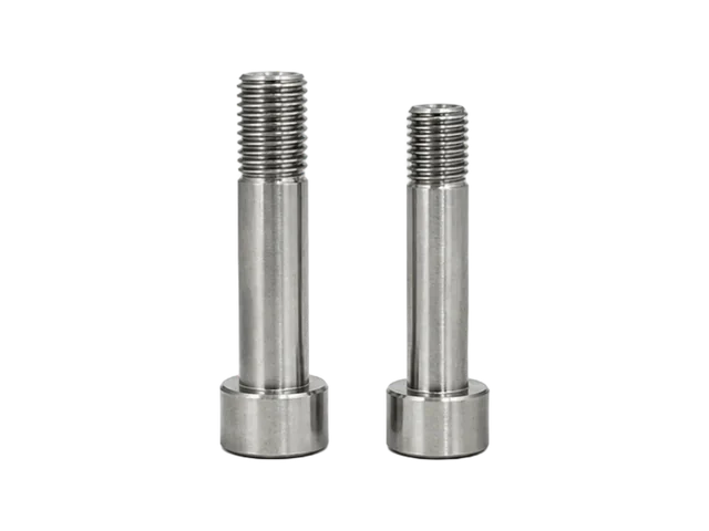
Original hardware illustrates a shoulder beside an external thread; it is a manufacturing geometry reference.
View original record →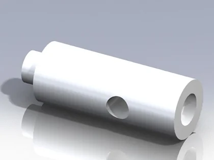
A shaft geometry reference for shoulder location, radial features and the relationship to a mating component.
View original record →A mounting distance should run between named faces. Identify whether a spacer ends at the bracket, a recessed seat or another sleeve. Show the bracket hole and any shoulder that locates in it, then specify which surfaces are expected to contact after assembly.

The PS-H03 Spacer Washer drawing shows how a ring-shaped part can be identified with its own diameter and thickness information. It remains a reference component. A new bracket stack requires its own drawing dimensions, seating conditions and relationship to the bolt or shaft.
Create a position list for the installation. For each position, record the customer part numbers, revisions and quantity of every spacer, sleeve and fastener. Note left/right or front/rear differences where the customer design uses them. This prevents visually similar hardware from being treated as interchangeable without an approved definition.
Specify the mating bracket and mounting-face materials alongside the requested hardware material. Use the materials review to discuss the nominated alloy and surface condition, and identify dimensions that apply after treatment. Include exposure and vibration-related requirements as engineering inputs with the intended acceptance method.
The manufacturing review can connect custom fasteners and precision component geometry to the relevant CNC turning scope. Additional operations, purchased mating parts and any installation work need to be identified in the quotation. The review is for defined accessory and bracket hardware, with vehicle compatibility set by the customer’s approved design.
Before sample manufacture, agree the component revisions, quantities and finished condition. State which mating pieces will be available for the customer installation check, what measurements are required and how approval will be recorded. An existing reference photograph supports a geometry discussion; a motorcycle application still needs its own fit and use assessment.
Send the accessory or bracket assembly drawing with the mating-surface detail. Identify the requested supply items and the evidence needed for the customer’s sample decision.
Yes. Provide both sides of the attachment and mark the hardware requested for supply. Include the mounting faces, hole relationships, separation and tool space. Open hardware details can then be identified for a drawing-led project review.
The customer assembly should identify the two faces or datums between which the installed separation applies. Include any recess, shoulder, washer or sleeve that contributes to that stack, and state the required finished condition.
Use a position-based BOM with each component’s customer part number, revision and per-position quantity. Show shared items and position-specific differences. This links the bracket drawing to the requested manufacturing and packing scope.
Model compatibility is defined by the customer’s approved installation requirements and sample assessment. Existing PremFixer references explain manufacturing geometry and original component details; they do not establish fit for an unspecified motorcycle or accessory.