
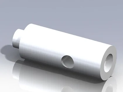
Technical rendering
PS-P02 Pivot Shaft
A shaft geometry reference for shoulder location, radial features and the relationship to a mating component.
View original record →Assembly function / Feature orientation
A shaft or pin with a flat, radial hole or other locating feature needs a defined relationship to the component it engages. PremFixer reviews customer-specified secondary features together with the shaft datums, axial station and functional direction. Show whether a feature provides retained orientation, accepts a separate pin or simply allows a tool to hold the part.
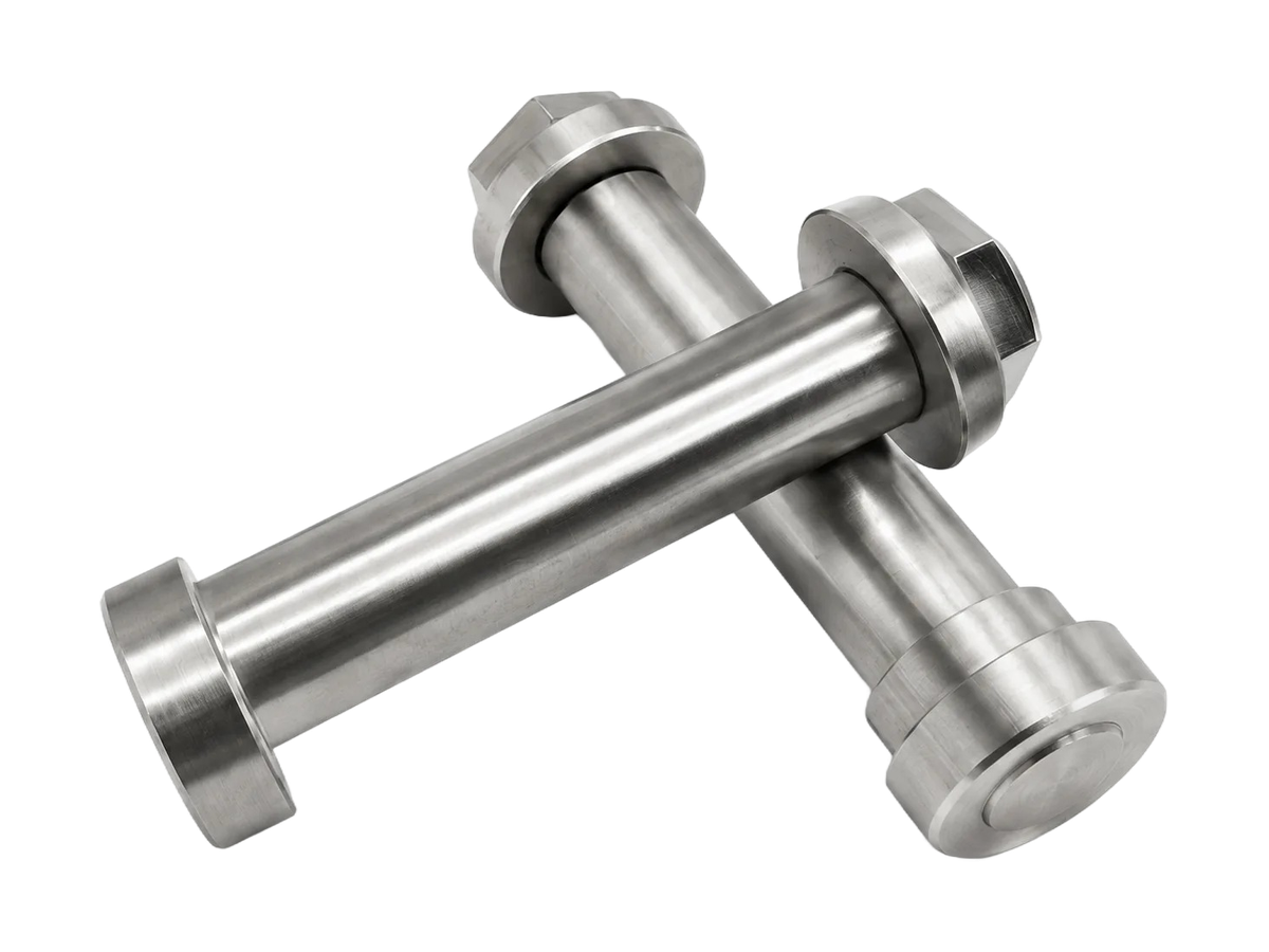
A visible flat can be a tool interface, a mating surface or an orientation feature. A radial hole may accept a pin or fulfil another drawing-defined function. Those uses create different review inputs even if the loose parts look similar. Identify the mating component and how it interacts with the feature in the approved assembly.
For retained orientation, show the direction that must be held and the reference that establishes it. For tool access, show the tool envelope and the installation step in which it is needed. A customer-specified slot can also be reviewed, but it must be present on the supplied drawing rather than assumed from these original shaft references.
PS-P02 and PS-P04 remain Pivot Shafts. Their technical renderings show a radial feature and wrench geometry respectively; the visible shape alone does not establish their original anti-rotation function. PS-D01 adds a separate drive and shoulder reference.
A shaft geometry reference for shoulder location, radial features and the relationship to a mating component.
View original record →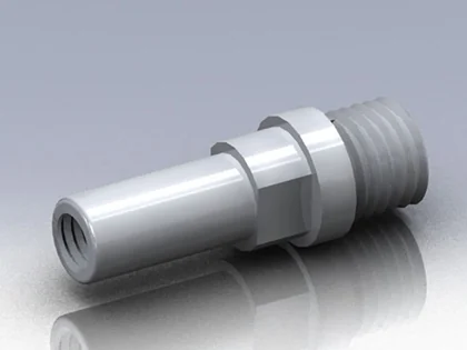
Reference for mating threads, stepped diameters and tool access. Its original identity remains Pivot Shaft.
View original record →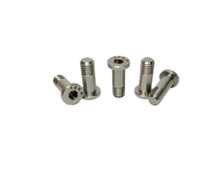
A small original product image used to discuss a recessed drive and shoulder, with the exact record linked.
View original record →Identify the datum used to locate the secondary feature along the shaft and the reference used to orient it around the shaft. A distance from the end may not communicate the intended relationship to a shoulder or another hole. The feature callout should connect to the part of the assembly that makes it functional.
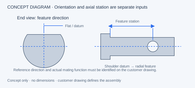


These original drawings retain their own dimensions and product identities. For a new shaft, provide the actual feature-to-datum relationship and any required angular relationship between separate features. Where the drawing leaves a direction unspecified, identify whether that direction is functionally free or needs customer approval before sampling.
The CNC turning review establishes the rotational geometry. The proposed route for holes, flats or other specified secondary features is then confirmed against the complete drawing. A feature photograph does not establish a machine configuration, one-setup process or universal angular accuracy.
Material and treatment requirements should identify the finished state of the relevant edges and mating surfaces. A burr at a radial-hole exit can affect assembly differently from an exposed non-contact edge. State the customer’s edge condition and inspection requirement rather than applying one generic note to every surface.
For samples, distinguish dimensions on the loose part from the customer’s functional check with the actual mating pin, key, tool or locating member. Record the approved drawing revision and the reference components used. If the feature belongs to a larger matched shaft assembly, include the related parts in the same review.
Send a drawing that identifies both the shaft geometry and the secondary feature’s function. Include the mating reference so an apparently minor feature can be reviewed in its actual assembly context.
No. They may provide temporary tool access rather than retained orientation. State the function on the customer drawing and identify the mating tool or component so the relevant dimensions and acceptance can be reviewed.
Use the datum scheme approved for the assembly, such as the shaft axis and a functional shoulder or face. Show the axial station and any orientation requirement. The appropriate reference depends on the mating component and the drawing’s design intent.
Identify both features and the datum that connects them. Provide the approved angular or directional requirement where the relationship is functional, together with the acceptance method. Flag any open requirement before sampling rather than inferring it from a rendering.
Nominate the edges that affect insertion, contact or handling and the dimensions that apply after treatment. Include radial-hole exits, thread intersections or mating flats where relevant. The inspection scope should follow the approved drawing and agreed sample plan.