
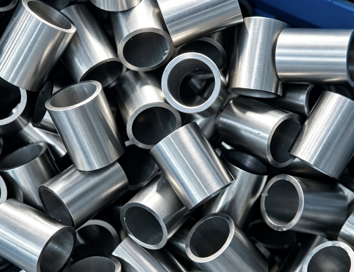
Sleeves and spacing components
Specify the mating diameter and the faces that establish spacing. Include the finished condition where a coating or treatment affects assembly.
For packaging and conveyor OEM projects
PremFixer manufactures drawing-defined shafts, pins, sleeves, spacers and custom fasteners for packaging and conveyor equipment projects. We work from your component drawings and assembly requirements, supporting prototype, pilot and repeat-production quantities. Roller-support interfaces, guide positions, retention features and individual part revisions are included in the manufacturing scope agreed for the order.
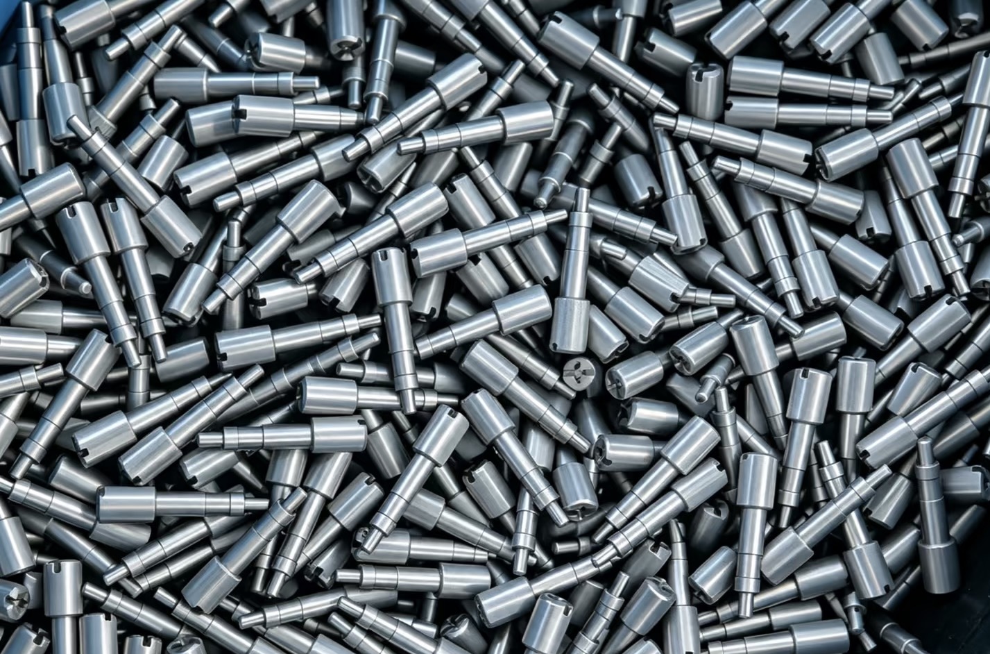
Build the procurement list around the mechanical assembly. We manufacture the shafts, pins, sleeves, spacers and threaded parts defined by your drawings, with each item's role and supplied condition agreed before production.
A roller support can involve a shaft shoulder, a mating bore, a spacer and a retaining item. Show which part fixes the axial position and whether the shaft stays stationary or rotates with the component.
Guide pins, mounting spacers and threaded adjusters need their own drawing references. Include the contact faces, adjustment travel and accessible tool positions that matter in the installed arrangement.
Specify the mating diameter and the faces that establish spacing. Include the finished condition where a coating or treatment affects assembly.
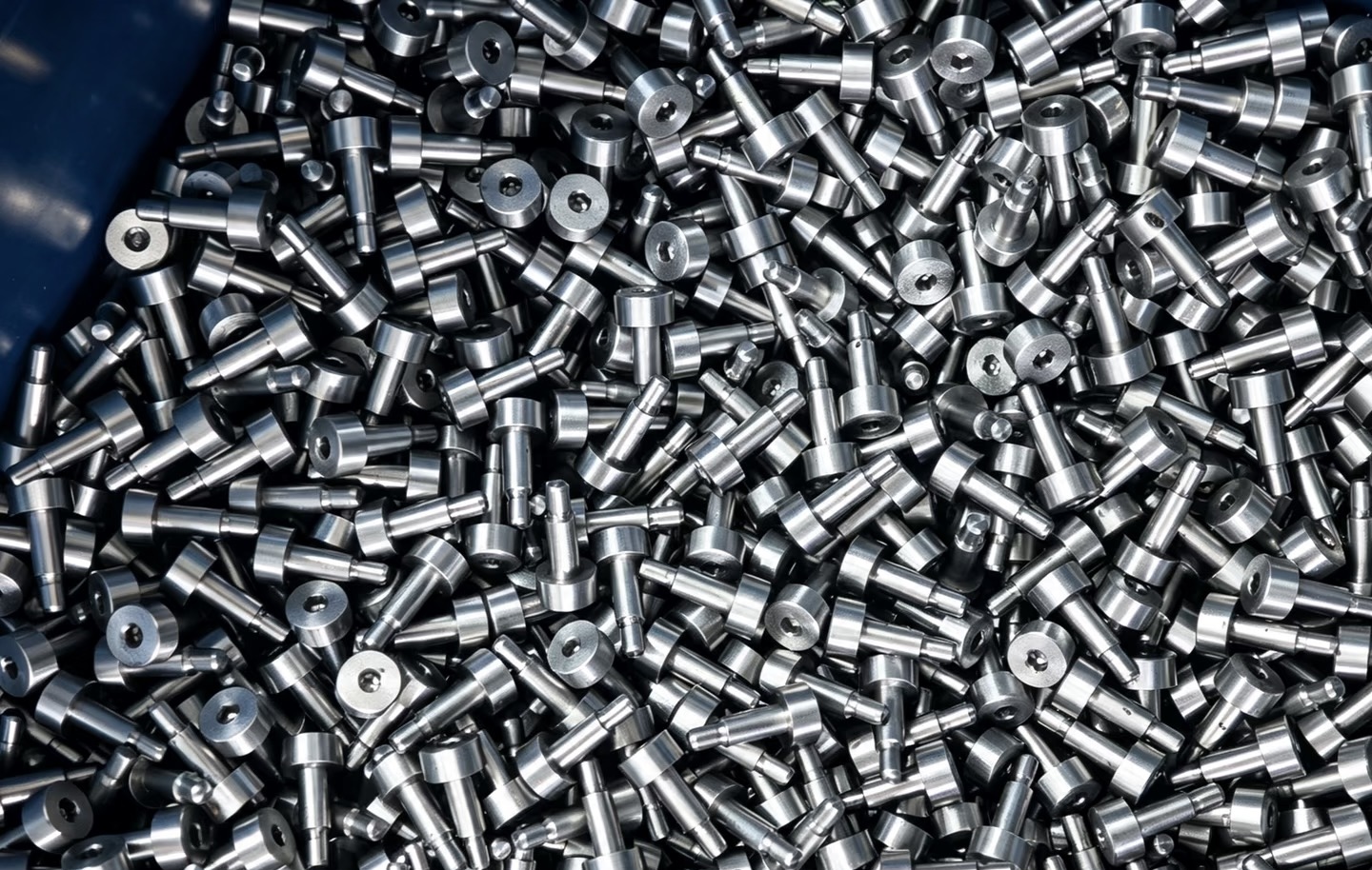
Locate the working shoulder from a defined datum. Stainless steel grade and finishing requirements come from the project specification, not the photograph.
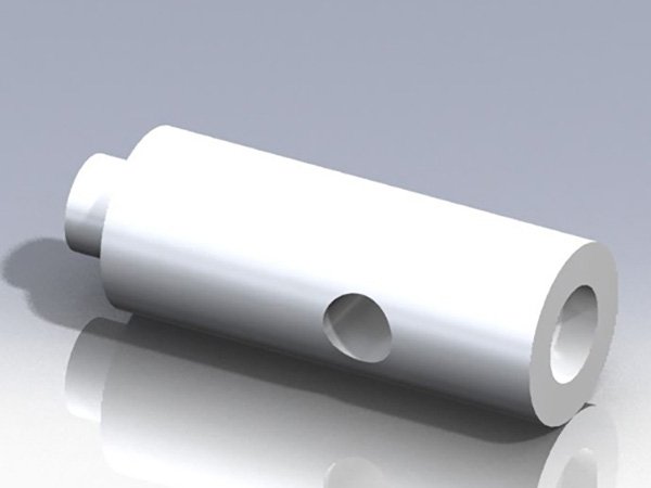
The original PS-P02 bicycle shaft rendering shows a useful feature combination. It illustrates geometry; it is not a conveyor part with established fit.
Two machine widths may share a spacer while requiring different shaft lengths. Identify which features remain common and which change. A family name, matching finish or similar photograph cannot distinguish the production items.
| Component / revision | Equipment variant | Length and shoulder control | Quantity per machine |
|---|---|---|---|
| SHAFT-A / Rev A | Width configuration A | DRAW-S-A; support seats and overall length | Enter the approved BOM count |
| SHAFT-B / Rev A | Width configuration B | DRAW-S-B; identify changed shoulder positions | Enter separately |
| SPACER-C / Rev B | Shared only if the BOM confirms it | DRAW-C; finished bore and axial width | Count for each configuration |
List extra service parts separately from the machine build quantity. For a requested sub-kit, define its contents and pack count; a complete line is not automatically one supply kit.
Show support seats, shoulder locations, mating bores and the retention arrangement on the component or assembly drawing. A cross-hole needs a position and orientation relative to the features that locate the part.
The original PS-P02 drawing is available at full resolution. Its existing dimensions belong to that reference part. Your roller-support drawing determines the dimensions, material, finish and inspection requirements for a new order.
Provide operating speed, loading, lubrication and cleaning conditions where relevant to the design review. The equipment designer approves suitability and system validation; manufacturing acceptance follows the agreed part requirements.

We manufacture drawing-defined forms in suitable steels, stainless steel, aluminum and titanium alloys. CNC turning and turn-mill machining address shoulders, bores, threads, cross-holes and flats. Material, shape, quantity and acceptance determine the route.
Identify cleaning chemicals, exposure, edge requirements and the supplied surface condition. Stainless steel alone does not establish food-contact suitability or hygienic design. Any project-specific evidence and testing must have an agreed scope.
Specified heat treatment, finishing and specialist testing are coordinated with qualified partners. Ask for the records needed for your supplier review and part acceptance; do not infer equipment ratings from a component photograph.
Separate the parts needed to check support positions from those needed for machine trials. State the sample purpose and current drawing status.
Provide quantities per machine and the number of pilot builds for each configuration. Identify the approved finish and any additional service spares.
Quote by controlled drawing or a defined hardware group. Preparation, machining, partner treatments, inspection and packing follow the accepted scope and batch quantities.
Reference the approved machine configuration and component revisions. Flag changed widths, support seats or retention details so a previous sample is not applied to a different arrangement.
Expected annual machine output helps planning. It does not replace the quantities and requested schedule for the purchase order being quoted.
Start with your contact details and the part or assembly information available. The most useful follow-up inputs are:
Long or heavy shafts and specialist process requirements need a specific drawing review. The quote identifies the component supply boundary.
Send Equipment Part DrawingsThe scope can include drawing-defined shafts, pins, sleeves, spacers and custom fasteners around the equipment assembly. Provide the component and mating-interface drawings so each requested item can be assessed. We supply the agreed components; this page does not represent a catalogue of complete rollers, conveyor lines or replacement machine systems.
Yes. Give each length variant a clear part reference and approved drawing revision, and state the quantity for that item. Identify any features that remain common and any that change with the equipment configuration. A single family name or photograph is not sufficient to distinguish different production variants.
Include the mating support arrangement, functional diameters, shoulder positions and retention details. State whether the shaft is fixed or rotating and identify the finished inspection requirements relevant to your design. Operating conditions can guide the review, but the approved drawing and acceptance plan define what the supplied component must meet.
State the actual material, cleaning environment, finish and required acceptance evidence in the RFQ. These requirements must be considered together with the geometry and mating components. Selecting stainless steel alone does not establish food-contact suitability, hygienic design or resistance to every cleaning process; any such requirements need an explicitly agreed scope.
Yes. Separate the pilot quantity from later batch demand and identify the applicable drawing revision for each stage. The quotation can address preparation, machining, finishing and agreed inspection accordingly. Production requirements or process changes are confirmed before release rather than inferred from the fact that a prototype was accepted.