
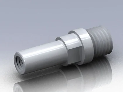
Technical rendering
PS-P04 Pivot Shaft
Reference for mating threads, stepped diameters and tool access. Its original identity remains Pivot Shaft.
View original record →Assembly function / Adjustment and clamping
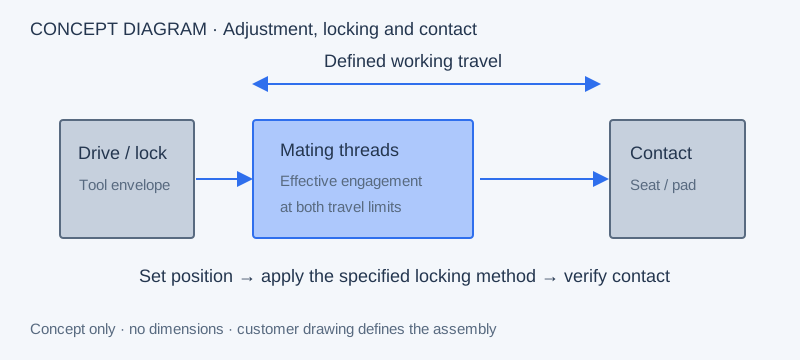
Threaded adjustment components move or position a contact surface through a defined working range, then use the specified locking arrangement to retain the setting. PremFixer reviews the threaded part and its mating components from your drawings. Show the required travel, effective thread engagement, drive access and contact condition at both ends of the working range.
An adjustment mechanism needs more than a thread size. The drawing should show which part moves, which member provides the mating thread, what surface receives contact and how the approved position is retained. A shoulder or threaded length may limit available movement before the overall part length becomes relevant.
Define the intended adjustment state as well as the locked state. Include the tool used to turn or hold the component and any reaction feature needed during locking. The customer’s approved mechanism requirements determine suitability; this review focuses on the custom hardware and its interfaces.
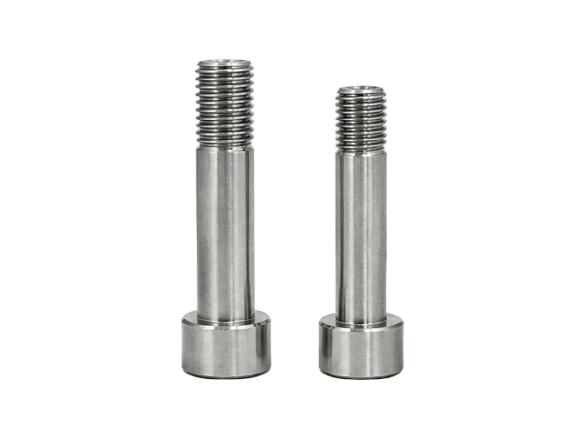
PS-P04 remains a Pivot Shaft; the other images retain their original bicycle hardware identity. Their threads, shoulders and drives help communicate manufacturing geometry. They do not represent a completed adjustment device or an established clamping-force rating.
Reference for mating threads, stepped diameters and tool access. Its original identity remains Pivot Shaft.
View original record →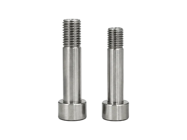
Original hardware illustrates a shoulder beside an external thread; it is a manufacturing geometry reference.
View original record →
A small original product image used to discuss a recessed drive and shoulder, with the exact record linked.
View original record →Identify the usable adjustment interval separately from the total threaded length. At each end of travel, show the intended thread engagement, clearances and contact location. If a locking nut or another retaining member is used, include its occupied space and the access needed to apply it.

The original PS-P04 drawing shows internal and external thread features alongside stepped diameters and wrench geometry. It is a useful reference for the type of information needed when multiple features share one part. The displayed dimensions remain specific to PS-P04.
For the new component, provide the datum and feature relationship that controls movement and access. If a wrench flat is used to hold the part while a separate nut is tightened, show both tool envelopes. For a contact tip or shoulder, identify the intended seating geometry and the relevant surface requirement rather than assuming it from the reference image.
State the proposed material, finish and contact-surface condition on the drawing. Discuss the mating threads and any customer-specified lubrication or locking provisions as part of the complete interface. The existing anti-loosening guide provides related considerations; the project still needs its own approved retention method.
Use the CNC turning review for the rotational geometry and the surface treatment page for finish scope. Secondary drive or locating features are reviewed against the actual drawing. The scope is custom threaded hardware, without extending a simple shaft reference into a ball screw, transmission screw or complete clamping mechanism.
Agree samples at the relevant assembly conditions. Component inspection should address the approved thread and dimensional requirements, while the customer’s mechanism check addresses movement, locking and contact. If repeated cycling or wear matters, supply the acceptance method and conditions as project inputs rather than relying on a generic performance statement.
Submit the moving member, mating thread and locking-part drawings together. A section at both travel limits helps expose engagement or tool-space questions before samples are prepared.
Show the start and end positions in the assembly and identify the thread engagement, contact point and limiting features at each position. Total thread length alone does not describe the usable working travel.
Include both drawings in the interface review even when only one item is requested for supply. If both are included in the quotation, give them separate part numbers, revisions, materials and quantities, plus the agreed sample acceptance conditions.
Identify the drive and holding features, then show the space available for the intended tools during adjustment and locking. Include adjacent components and the installation sequence when these restrict access to a hex, flat or recessed drive.
Specify the mating member, contact location, surface geometry and required material or finish condition. If contact behaviour or wear is an acceptance requirement, provide the customer’s method and operating conditions for review.