
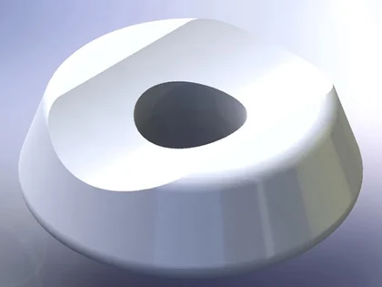
Technical rendering
PS-H02 Spacer Washer
Reference for end-face contact and bore clearance; confirm the manufacturing route against the new drawing.
View original record →Assembly function / Static mounting
Mounting spacers and standoffs establish a fixed separation between components while preserving the required hole alignment, support faces and tightening access. PremFixer reviews through sleeves, threaded standoffs and shouldered mounting parts from your drawings. Define the mounting distance at each position, the fastener or mating thread and the finished surfaces that support the assembly.
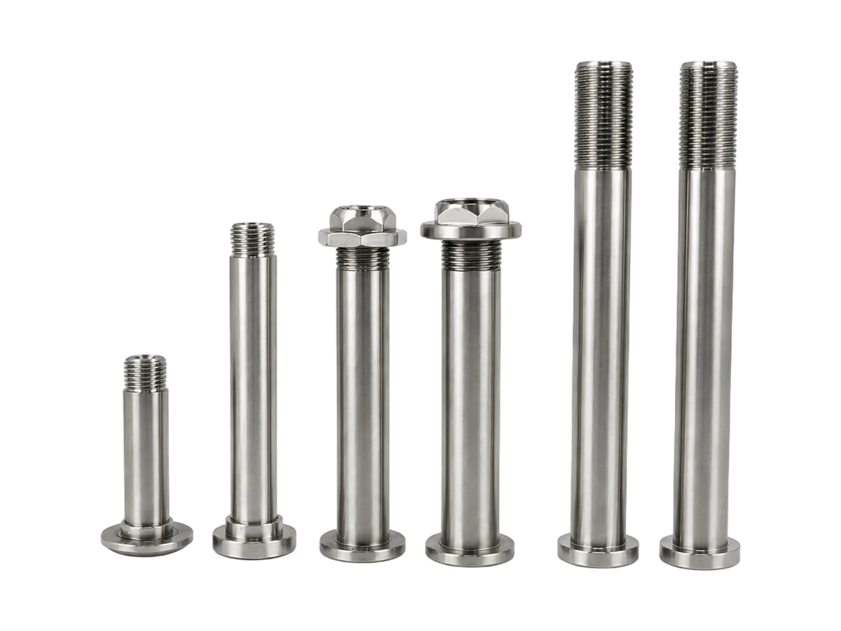
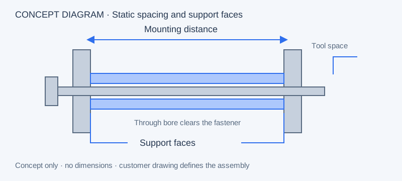
A through sleeve provides a passage for a separate fastener. A threaded standoff adds a defined mating thread, while a shouldered mounting sleeve can also locate within a hole or recess. The name alone does not establish which surfaces carry the clamping force or which diameter aligns the components. Show those functions in the mounting section.
Mark the two support faces that control static separation. A surrounding diameter may be a clearance feature even when it appears concentric with the fastener. Keep tool access in the same review: the drive and reaction surfaces must remain accessible in the intended installation order.
PS-E10 is a cold-headed sleeve reference; PS-H02 is a technical rendering. The new drawing determines the requested manufacturing route.
Reference for end-face contact and bore clearance; confirm the manufacturing route against the new drawing.
View original record →
Through-hole sleeve geometry reference. The existing record lists cold heading; a new project route requires review.
View original record →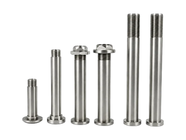
A length-family reference. Every new length and assembly position needs its own drawing identification.
View original record →Provide a section through the bracket, mounting sleeve and fastener. Show the contact face on each side, the mating holes and any recess that positions the sleeve. This allows the quotation review to separate length control, radial location and the passage needed by the fastener.

The original PS-H02 drawing provides a specific ring-shaped reference. For a mounting family, supply a dimension table or separate drawings that identify each required length and its assembly position. Avoid identifying similar pieces only by a photograph or a position description that changes between documents.
A useful family register links the customer item number, revision, length, mating thread, quantity per location and label requirement. Shared geometry can be identified once, while differing faces or shoulders remain item-specific. Confirm whether samples are required at every position or at a customer-approved selection of configurations.
Motor or controller mounting: identify the bracket or cover mounting holes, stand-off distance and tool envelope. Include the adjacent mechanical surfaces that constrain installation. The requested scope is the spacer and fastening hardware; the electrical assembly is a separate customer-defined system.
Battery-enclosure mounting: supply the enclosure mounting faces, mechanical retention relationship and quantities at each fixing location. Separate the hardware’s seating requirements from sealing or battery performance requirements, and show any clearance needed around the housing. These are mounting scenarios within this page, with their own drawings and acceptance inputs.
Specify material and finish through the materials review, including any surfaces that require a different treatment or acceptance condition. The CNC turning page explains the drawing review for rotational features; any additional operations remain part-specific.
Samples should be identified by position and checked against the nominated mating holes and support faces. Agree dimensional inspection and any customer assembly confirmation before production. Where a project contains several lengths plus fasteners, the system manufacturing review connects the individual drawings, per-position quantities and packing groups.
Include a mounting section and a position list. A separate drawing for the bracket or mating plate helps explain what locates, what supports and what only clears the hardware.
Its drawing defines the separation between fixed components, the surfaces that support them and the passage or thread used by the fastener. Include locating shoulders and clearance features separately so the manufacturing review follows the intended mounting function.
Yes. List every length with a customer item number, revision, assembly position and quantity. Mark shared features and any exceptions. The sample plan and packing requirements should make similar components easy to distinguish.
Provide the hole and recess geometry that locates or clears the spacer, together with the relevant position reference. Identify the surrounding support face and the separate fastener where applicable. A mounting section is usually the clearest way to communicate the relationship.
Nominate the finished support faces, locating diameters, threads and other dimensions that must meet the approved drawing. Specify treatment exclusions or cosmetic requirements separately, so the agreed inspection addresses the surfaces that matter in assembly.