
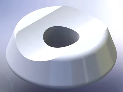
Technical rendering
PS-H02 Spacer Washer
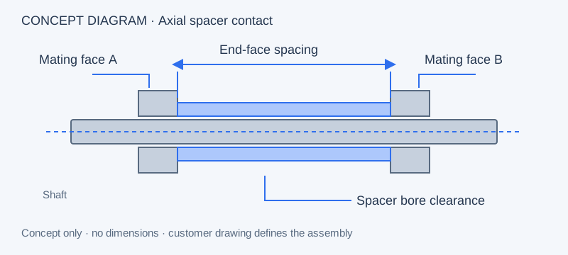
Reference for end-face contact and bore clearance; confirm the manufacturing route against the new drawing.
View original record →Assembly function / Axial spacing
Custom bearing spacers establish an axial distance between defined contact surfaces in a shaft and bearing assembly. PremFixer reviews spacer rings and sleeves against your assembly section, mating components and finished-state requirements. Identify which faces contact the bearing or shaft shoulder, which diameters locate the part and which surfaces simply provide clearance.
A spacer can sit between two bearing inner rings, between an inner ring and a shaft shoulder, or within a separate support stack. These positions create different contact requirements even when the loose components look alike. Mark the actual contact faces on the section view so the review follows the intended load path.
Separate locating surfaces from clearance surfaces. A bore may centre on a shaft, or it may only clear the shaft while the end faces define the spacing. Likewise, the outside diameter may locate in another component or need space around a seal or housing. The drawing should identify these functions before tolerances or manufacturing steps are discussed.
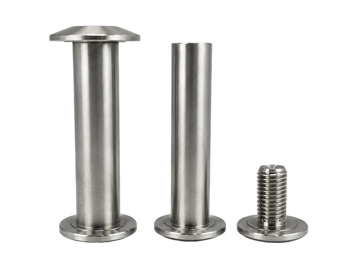
The PS-H technical images show two spacer forms; PS-E10 supplies a through-sleeve reference. Their original identities and records remain linked. The process for a new spacer is assessed from its drawing, rather than inferred from the shape of these examples.
Reference for end-face contact and bore clearance; confirm the manufacturing route against the new drawing.
View original record →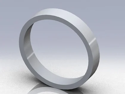
Reference for a ring-shaped spacing element. The original record and drawing retain their own dimensions.
View original record →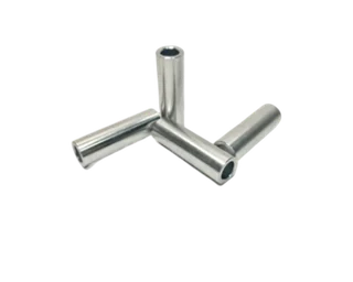
Through-hole sleeve geometry reference. The existing record lists cold heading; a new project route requires review.
View original record →Show where the spacer begins and ends within the stack, and identify the adjacent parts by drawing or purchased-part reference. A target gap alone does not show whether a shoulder, bearing ring or additional washer establishes the datum. Include the intended seating condition so the relevant dimensions can be read together.

The original PS-H03 drawing is a reference for communicating a ring’s diameters and thickness. Its dimensions apply to that specific component. For a new part, provide the required spacing and the associated shaft, bearing or housing references, together with any face orientation or surface requirements.
A tolerance value becomes meaningful only within the complete dimension chain and inspection method. Supply your approved dimensional limits or identify the assembly result the engineering team must review. Spacer dimensions alone do not establish bearing preload, service life or noise performance; those outcomes need the customer’s complete assembly assessment.
Use the materials guide to identify the specified alloy and condition. State whether coating, anodising or another treatment applies before final dimensional acceptance. Keep contact-face requirements separate from purely cosmetic surfaces, and identify any treatment exclusions needed by the drawing.
The CNC turning review can assess the requested rotational geometry and secondary features. For samples, name the mating shaft and bearing reference used to check seating and clearance. A spacer can also be included with its shaft or locking part in a multi-part manufacturing review, with item-level inspection and assembly confirmation recorded separately.
Send the spacer drawing with an assembly section. If an interface is still open, highlight it and identify who will approve the final dimension chain.
It is a useful mating reference, but the spacer review also needs the assembly section, shaft or shoulder geometry and required spacing. Show which bearing faces make contact and whether the spacer bore locates or clears the shaft.
The customer drawing should nominate the end faces that seat against adjacent components and define the axial distance. Faces that only provide clearance should be distinguished. An assembly section helps connect these surfaces to the complete dimension chain.
State the acceptance condition explicitly. If a surface treatment is included, identify which finished dimensions and contact surfaces must meet the drawing. This supports a review of the complete manufacturing route and the sample inspection plan.
Yes, supply both drawings and the assembly relationship. List separate part numbers, revisions and per-assembly quantities. The quotation can then distinguish each component’s requirements from any agreed paired sample review.