
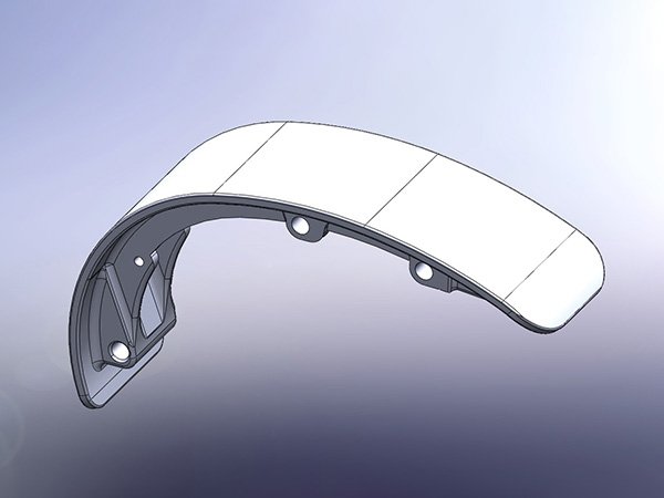
PS-R02
Motor-interface cover
Curved cover geometry with mounting locations shown in the drawing.
View productConnect motor-interface covers, frame inserts and cable-routing hardware to your e-bike drawing and assembly requirements.
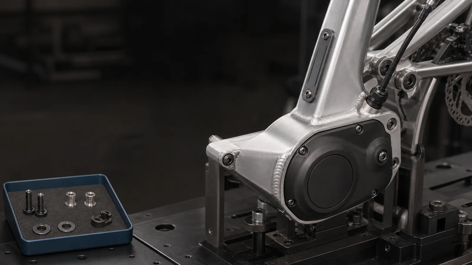
Browse cover, insert and routing references together. Confirm the exact motor platform, frame revision and supply scope for your assembly.
Curved cover geometry with mounting locations shown in the drawing.
View product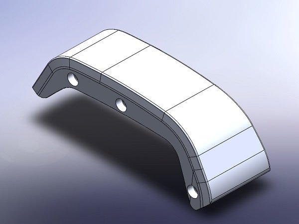
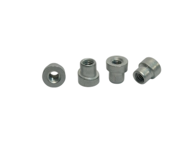
Threaded frame attachment geometry to compare with your drawing.
View product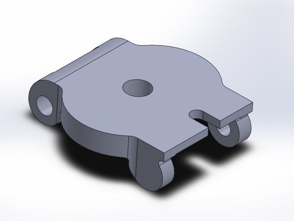
Cable guide geometry for the specified frame routing arrangement.
View product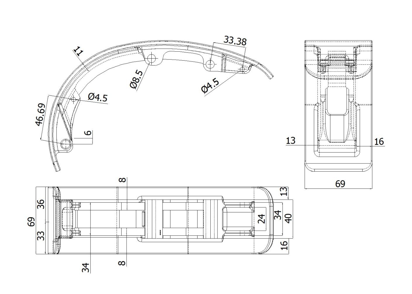
PS-R02 drawing reference. Open the product page to review the full-size geometry.
A motor designation is only one part of the specification. The frame drawing defines the mounting locations and surrounding hardware.
Locate mounting faces, holes, clearances and fastener directions against the motor and frame assembly.
Review cover edges, fixing points and any frame insert or bracket included in the BOM.
Identify cable paths, entry locations, guide geometry and space around adjacent components.
Check access for installation, removal and service with the surrounding parts in place.
Start with the available drawing and quantity. Add the material, assembly and inspection details as they are defined.
Review material optionsProvide the motor model and version together with the frame or assembly drawing. Product references do not establish universal interchangeability between platforms.
Specify material, condition, finish and critical dimensions. The manufacturing route is reviewed for the supplied geometry and order requirements.
Share the sampling quantity, production requirement and needed inspection records. Identify any project-specific testing, labelling or packaging during quotation.
Send a drawing, sample reference or BOM with the quantity and application. Open details can be discussed during the project review.
2D drawing, STEP file, BOM, or physical sample information.
Prototype, first production order or repeat requirement.
Share the interface, material or assembly questions you already know.