
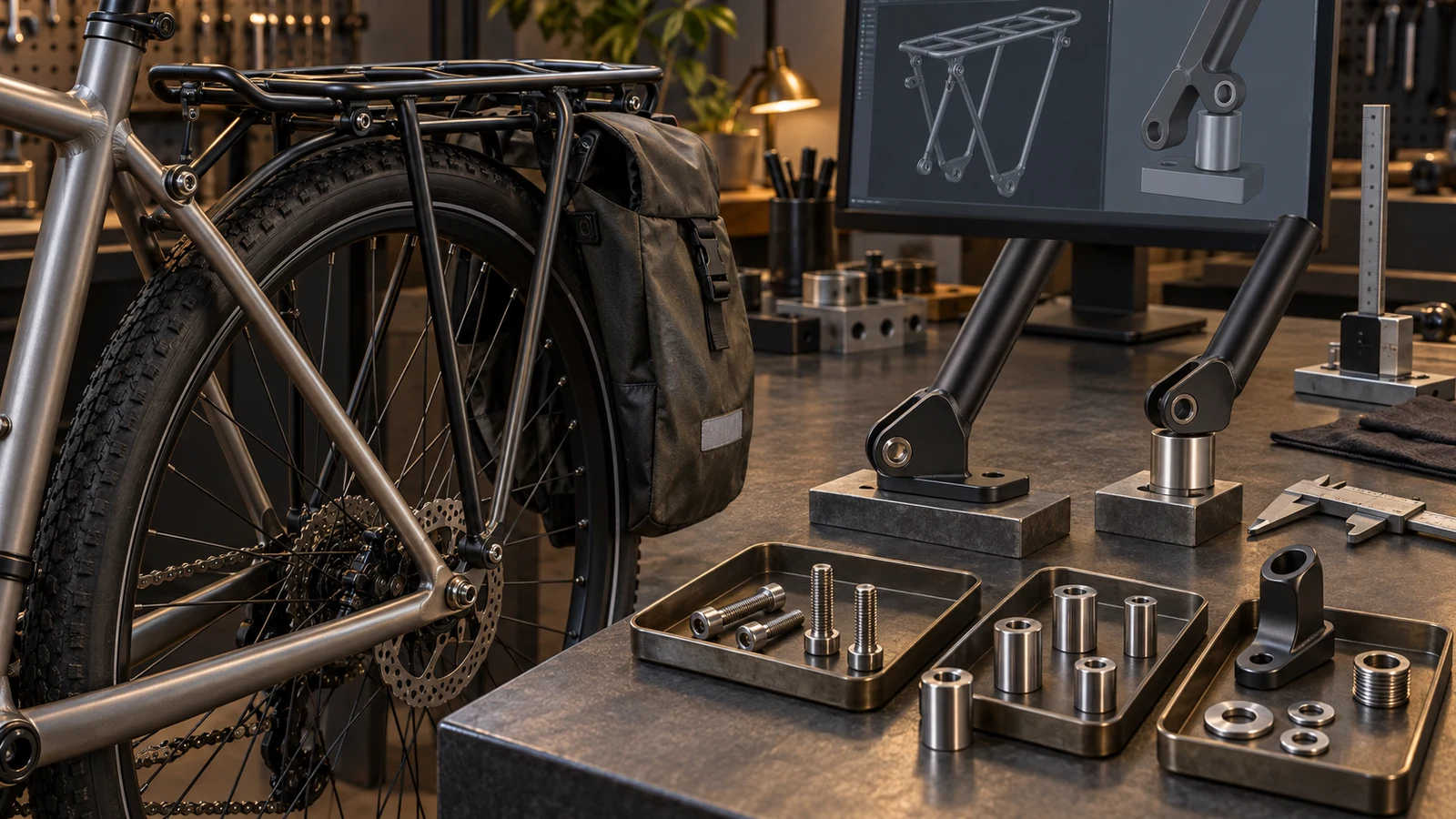
One bicycle rack bolt does not have a universal cargo rating. The permitted load belongs to a defined rack, bicycle and mounting arrangement, not a screw material in isolation. Before ordering custom hardware, identify the lower rack feet, upper stays, frame eyelets and any adapters or spacers. A longer bolt may clear a brake but also change the rack-foot support and offset. Review the actual contact, receiver engagement and use conditions together. Do not multiply bolt capacity by the number of mounts, or assume stronger stainless hardware and a locking washer approve a greater payload.
Hero: concept illustration of example hardware and its application. It is not a factory photograph, tested component or approved production geometry.
Locate the supports before assigning load to a bolt
Show the rack platform, feet, upper stays and bicycle mounting points on an assembly view. Identify which attachment locates or supports each rack member and which frame or adapter receives the screw. A rear rack, front lowrider and seatpost-mounted carrier do not share one mounting definition.
Record the intended luggage arrangement and mounting configuration. A pannier beside the wheel and luggage above the platform place their loads differently. Engineering analysis must relate these conditions to the supports; dividing a payload evenly by the fastener count does not establish the forces at each connection.
Keep this mounting decision separate from a cargo bicycle's moving mechanism. The cargo-pivot guide reviews shafts and moving contacts; this article concerns rack brackets, receivers and mounting hardware rather than an assumed suspension pivot.
Compare direct contact with a clearance spacer
For a direct mount, show the rack foot seated against its intended mounting surface. Check that the bracket can reach that surface in the specified orientation without being pulled into place by the screw. Tubus's FAQ addresses parallel rack feet and avoiding mounting tension for its products.
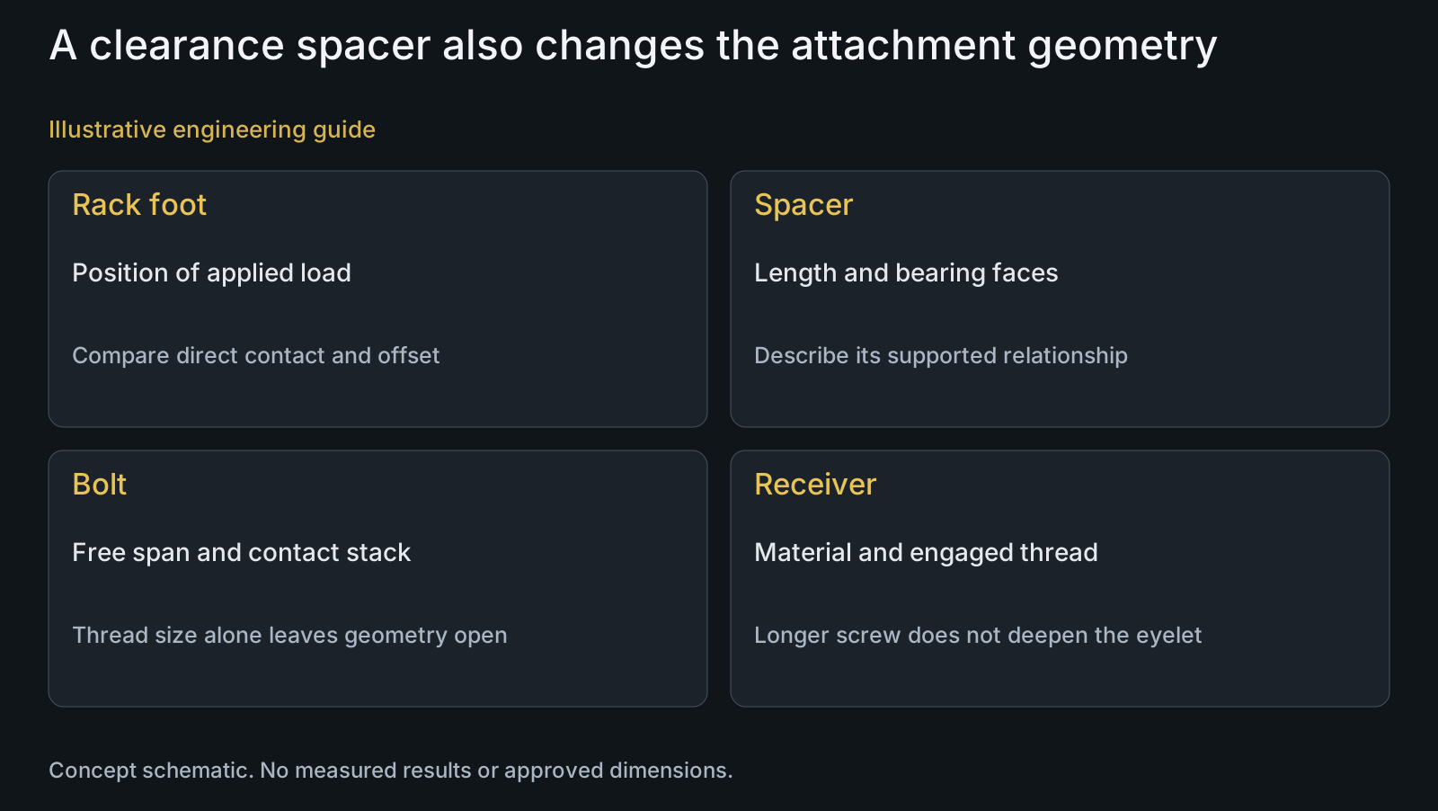
For a spacer arrangement, state its length, contact faces and how it is supported. The bolt's free span and the foot's offset may change. Engineering analysis: a load acting away from a support introduces a moment relationship that a nominal screw-strength comparison leaves unresolved.
Do not prescribe a universal maximum spacer length. Assess the defined geometry, receiver and intended load cases. An approved carrier-specific adapter is also not equivalent to a collection of loose washers chosen to fill the same gap. Identify the candidate arrangement rather than calling all clearance solutions interchangeable.
| Arrangement or change | What changes | Risk of a shortcut | Review basis |
|---|---|---|---|
| Rack foot seated directly | Defined contact at support | Screw pulls a misaligned foot into place | Mounting surfaces and applicable instructions |
| Added clearance spacer | Offset, contact faces and bolt span | Only extra screw length is considered | Assembly section and connection assessment |
| Carrier-specific adapter | Mounting method and possible load limit | Original rack rating automatically retained | Exact adapter and maker's scope |
| Longer screw in existing eyelet | End clearance and available thread | Extra length called extra engagement | Receiver depth and nearby clearances |
| Changed bolt grade or alloy | Component properties and final state | Stronger bolt called higher cargo capacity | Part definition plus complete mounting evidence |
| Locking washer or other retention | Contact and locking condition | Retention device called structural approval | Specified stack and assembly requirement |
Inspect the receiver and clearances with engagement
Specify the frame eyelet or adapter thread, receiving material, usable depth and effective engagement. A longer screw does not create more engaged thread beyond the receiver. Distinguish a blind hole from a through feature and show the relevant bottom or exit clearance.
Include clearance to nearby brake, wheel, axle, tyre and other hardware in the represented configuration. State which clearances change with the proposed spacer or screw. Avoid specifying length solely from the rack-foot thickness while omitting where the screw end will finish.
Use the effective-engagement guide for the receiving relationship and custom fit drawings for defined locating contacts. Neither provides a universal eyelet strength or a compatible adapter for an unnamed frame.
Treat adapters and accessory limits as configuration-specific
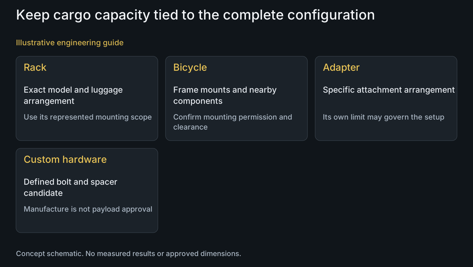
Tubus states that specified mounting accessories can reduce the allowed load of a carrier with a higher original rating. This is a manufacturer-specific example of why a changed attachment can have its own limit. It does not supply a transferable load rating for custom PremFixer bolts or another rack.
The same FAQ restricts its clamp sets on carbon frames without suitable eyelets. Do not extend a metal-frame attachment method to another frame material without the relevant maker's permission. A bolt that fits an adapter does not establish the adapter's suitability for that frame.
For a custom OEM arrangement, identify the rack, frame, adapter and accessory revisions together. The compatibility guide supports that definition. Service replacement parts must follow the applicable component instructions; a manufacturability review is not authorization to alter an existing rack system.
Keep locking and material choices within the joint definition
Specify bolt material condition, head contact, final surface and the intended locking method. A locking washer addresses a particular retention arrangement; it does not rate the receiver, remove an offset or prove fatigue life. Do not add it to every mounting point without evaluating the contact and assembly instructions.
Discuss custom geometry through CNC turning, candidate materials and functional finish through surface treatment. State which dimensions and contacts apply after processing. Stainless is not a category-wide substitute for a complete component specification.
ISO 11243:2023's public scope covers safety and performance requirements for bicycle luggage-carrier design and testing within its stated application. It does not provide a bolt-only cargo number. Any system claim needs the relevant requirements and represented assembly evidence, not an unexplained safety factor.
Review example: brake clearance changes the rack foot
Illustrative engineering example: assume an OEM needs clearance between a rear rack foot and a brake component. It proposes a longer screw and a cylindrical spacer at one lower mount while retaining the rack and frame eyelet. No load, dimension, calculation or test result is assumed.
The reviewer compares the original direct contact with the proposed offset, including spacer faces, bolt span, receiver engagement and nearby clearances. It also identifies the rack and frame's mounting permissions. A stronger screw might address one defined component concern, but would not restore the original supported geometry.
The RFQ can therefore define a custom bolt-and-spacer candidate and the attachment evaluation it requires. The team must not advertise unchanged or increased cargo capacity until the responsible product owner has established that configuration's acceptance basis.
Questions buyers need to confirm
How much load can one bicycle rack bolt carry?
No universal cargo value follows from the bolt alone. Identify the complete rack and bicycle mounting arrangement, receivers, contacts, luggage placement and operating requirements. The permitted cargo limit must come from the applicable represented-assembly basis.
Can rack capacity be divided by the number of bolts?
Not as a connection assessment. Load placement and support geometry determine the relationship at each mount. Upper stays and lower feet can serve different tasks; equal fastener counts do not establish equal forces.
Does a longer screw solve brake-clearance interference?
It may form part of a defined candidate, but it also needs a supported spacer, contact and clearance review. State the offset, bolt span, receiver depth and surrounding components. Extra length alone does not approve the attachment.
Can an adapter retain the rack's original capacity?
Do not assume so. Check the exact adapter and carrier instructions; a mounting arrangement can have a lower limit than the carrier alone. A manufacturer's limit for its own accessory is not a rating for a custom copy.
Will stainless bolts and locking washers approve a heavier load?
No. Material and retention address defined component questions, not every receiver or support limitation. Specify the final part and locking condition and evaluate the complete attachment. Neither establishes a universal cargo increase.
What should a custom rack hardware RFQ contain?
Send rack/frame identities, mounting drawings, STEP or represented samples and BOM. Include bracket contacts, spacer geometry, eyelet material/thread/depth, clearances and intended luggage configuration. Provide applicable assembly and load requirements, distinguishing part conformity from system acceptance.
Technical references and scope
Tubus mounting and accessories FAQ. Manufacturer-specific rack-foot alignment, mounting-accessory limits and carbon-frame clamp restriction. No numeric rating, adapter compatibility or service procedure transferred.
ISO 11243:2023 public scope. Bicycle luggage-carrier safety/performance design and testing scope only. No paid test clauses or universal bolt capacity claimed.
Explore related component, material and sourcing decisions in the customer decision knowledge center. For a drawing review, use the Drawing/BOM RFQ path.
Review rack bolts and spacers with their actual mounts
Share the rack and bicycle configuration, marked attachment drawing, STEP or samples and BOM quantities. Include rack-foot contacts, spacers or adapters, eyelet thread and usable depth, nearby clearances, material/finish and applicable load and assembly requirements. PremFixer can review drawing-defined mounting hardware while the responsible product team controls complete-system capacity approval.
Discuss the drawing and BOM