
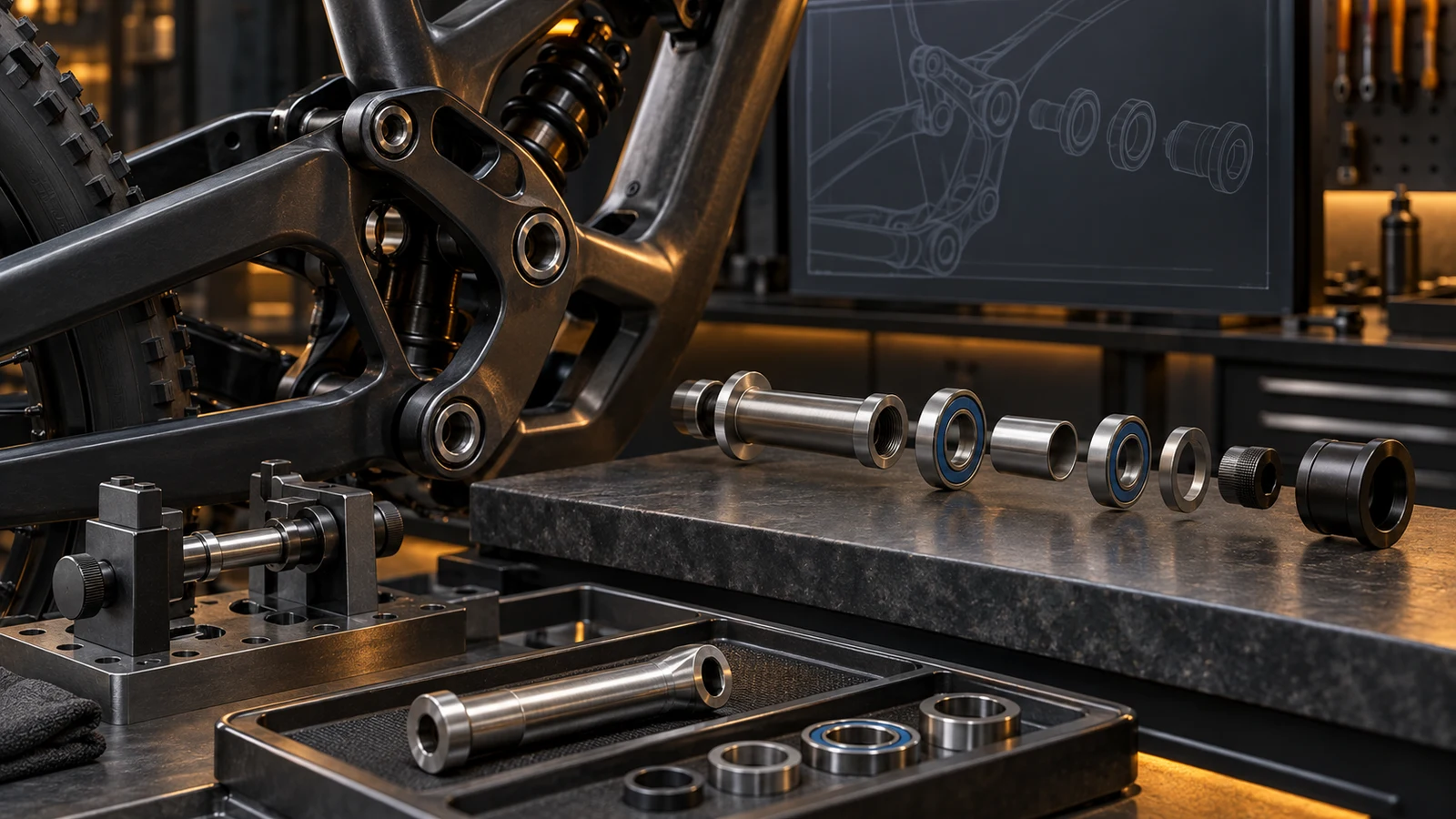
Integrate a custom pivot bolt with the frame by defining where the joint locates, where tightening force is reacted and where movement is intended. Review the axle, bearing rings, internal and external spacers, frame ears and retaining hardware together. The engineering decision is whether the finished parts and assembly method preserve those functions, not simply whether a bolt can pass through the holes. A satisfactory insertion check does not establish correct clamping contact, bearing behavior, load capacity or service access. Start with the assembly section and mating specifications, then resolve the manufacturing and verification questions against that particular configuration. DFM supports the designer's decisions; it does not replace frame validation.
Hero: concept illustration of example hardware and its application. It is not a factory photograph, tested component or approved production geometry.
Map location, clamping and intended movement separately
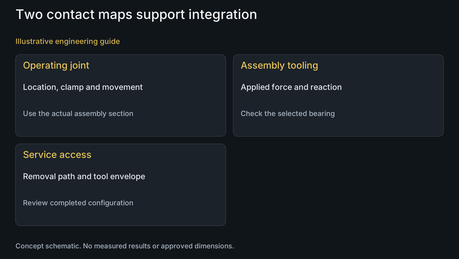
In the assembly section, identify each surface that locates a component and each face that transmits tightening force. Also identify which parts move relative to one another during pivot operation. These roles need not belong to the same surfaces, and the answer changes with the actual bearing or bushing arrangement.
For a proposed bearing-supported axle, determine how each ring is supported and retained. Do not infer the axial contact arrangement from a convenient exploded image. A spacer, shoulder or end cap can establish a different contact boundary even when the axle's nominal diameter remains unchanged.
Use the drawing fit review for individual mating limits and geometric controls. This integration review asks whether those specified interfaces work together with the frame's intended function, rather than recommending one fit designation for every pivot.
Resolve the axial contact chain before tightening
Identify the surfaces that close against one another as the retaining hardware is tightened. Compare the axial stack with the intended ring and spacer contacts. A missing contact, unwanted gap or contact against a moving surface requires a different response from a shaft diameter that prevents insertion.
Do not use additional tightening as a general cure for an undefined stack. First establish what is expected to become seated and what must retain its intended movement. Torque, lubrication and receiver engagement require their own approved basis; no universal installation value is assigned here.
Include shoulder reliefs, edge breaks and adjacent geometry in the contact review. A drawing can show sufficient axial length while a corner prevents the expected seating. Review the selected bearing's actual interface requirements rather than borrowing a corner or abutment dimension from an unrelated component.
| Interface or activity | Decision input | Risk if overlooked | Useful check |
|---|---|---|---|
| Axle location | Mate, final limits and functional datum | Nominal fit hides mislocation | Finished mating and geometry review |
| Axial clamping | Ring, spacer and face contact chain | Tightening closes the wrong surfaces | Assembly section and defined seating |
| Finished surface | Treatment, masking and acceptance state | Pre-treatment fit misrepresents delivery | Inspect controlled delivered features |
| Bearing mounting | Ring fitted and tool reaction | Force crosses unintended contacts | Tool-contact and sequence review |
| Service access | Socket, withdrawal path and neighbors | Assembled linkage blocks removal | Completed-configuration access check |
| Joint validation | Loads, use conditions and authority | Assembly fit treated as durability proof | Designer-owned validation plan |
Make tolerances describe the delivered assembly condition
Compare the permitted mating ranges, not only nominal dimensions or one fitted prototype. Relate radial interfaces, axial lengths and relevant geometry to the functional datums. Tightening one isolated tolerance cannot resolve an undefined opposing surface or a changed mating component.
Identify which controlled surfaces are accepted after treatment, and which are masked or otherwise processed differently. The surface-treatment review can address the proposed supplied condition. A pre-treatment measurement is process information, not automatic acceptance of a drawing-controlled finished interface.
Connect the requirements to the CNC turning route: tool access, locating arrangement, datum transfers and inspection of finished features. PremFixer manufactures drawing-defined hardware within its confirmed scope; it does not silently select the OEM's bearing fit, frame deflection allowance or validation limits.
Review assembly and service tool contacts
Draw the mounting tool and its reaction support as well as the assembled parts. NSK's mounting guidance explains that cold-mounting force belongs on the bearing ring being interference fitted, rather than through the rolling elements. This is a mounting principle, not a prescription that every bicycle pivot requires the same interference fit.
Apply that principle to the selected bearing and assembly sequence. Can a fitting cup reach the intended ring before the linkage closes access? Does the reaction support contact the correct member? A suitable tool for the loose bearing may become unsuitable once a frame ear or cap blocks its path.
Review disassembly too. Identify how the axle is withdrawn, how the retaining hardware is reached and which neighboring surfaces require protection. A socket that reaches the fastener on a bare frame may be obstructed by a completed linkage. Do not promise serviceability from a manufacturing sample alone.
Separate virtual clearance, assembly behavior and validation
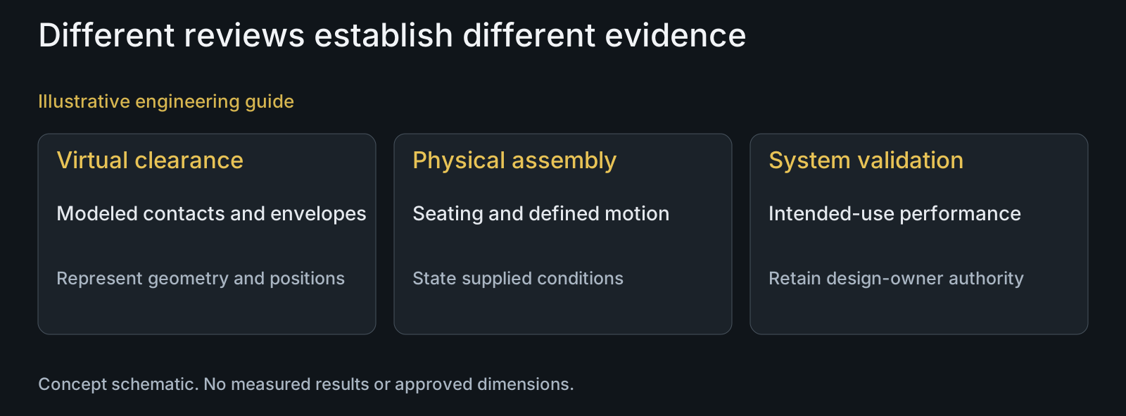
A CAD clearance review can identify proposed interference and tool-envelope conflicts in the modeled configuration. It does not by itself establish the behavior of finished bearing interfaces, lubrication, elastic members or treatment-dependent contact. State which geometry and positions were included rather than report a general simulation pass.
A physical assembly review can examine insertion, seating, contact, retention access and defined motion under specified conditions. Link each observation to a question. A sample that moves freely before tightening provides different evidence from the same assembly under its approved retention condition.
Frame loads, fatigue and intended-use validation remain with the responsible design and validation parties. Prototype manufacture supports examination of a defined configuration, but cannot convert DFM advice into a certified frame result. Retain the particular components and conditions represented by each review.
Illustrative review: a revised end cap
Illustrative engineering example: assume an OEM retains an axle drawing but proposes a wider end-cap flange for a new linkage shape. The bearing arrangement, spacer geometry and frame-ear contact still need confirmation. No torque, tolerance, load result or customer case is supplied.
The team first asks whether the flange contacts the intended stationary surface or overlaps a member that must move. It then examines whether the mounting cup and service socket can still reach their intended contact points. An unchanged axle diameter would not answer either question.
If the revised geometry resolves access in CAD, a representative assembly can examine the named contacts and motions under the agreed conditions. The designer decides what further validation is required. The example demonstrates two independent contact maps without inventing an approved configuration or a successful test outcome.
Questions buyers need to confirm
Does an axle that fits through the frame prove integration?
No. It establishes only the represented insertion behavior. Confirm the locating surfaces, clamping contact chain, ring restraint, finished condition and accessible tools. Those fields determine whether the assembled joint preserves its intended movement and retention.
Can higher tightening torque compensate for an uncertain spacer stack?
Do not assume so. Identify the surfaces intended to seat and the stack that connects them. Undefined contact can load an unintended member. The approved retention method, lubrication and receiver engagement need review rather than an invented torque increase.
Why include mounting tools in the DFM review?
Their contact and reaction surfaces can determine whether the selected bearing can be installed without unintended loading. Provide the ring being fitted, fit basis, tool envelope and sequence. A clear final assembly drawing may still omit an inaccessible mounting path.
Can CAD motion review replace physical assembly checks?
Not generally. It can examine the modeled geometry and positions, while finished fits, actual contacts and assembly behavior require appropriate evidence. Record what the model includes and select physical checks for the questions it cannot resolve.
Does DFM replace the frame designer's validation?
No. It supports manufacturing and interface decisions within the supplied hardware scope. Intended loads, durability and whole-frame acceptance remain with the responsible design and validation parties. An acceptable machined sample is not a validated bicycle system.
What should be supplied for a joint-level review?
Send the assembly section, STEP geometry, mating-part specifications, BOM revisions, materials, treatments, intended operation and assembly method. Add prototype needs and any tool or service restrictions so the review can identify which contact or access decision is blocked.
Technical references and scope
NSK, Bearing Maintenance Tools: correct mounting. Manufacturer guidance on applying cold-mounting force to the interference-fitted ring and avoiding force through rolling elements. No source percentage, product promise or industrial fit assignment transferred to bicycle pivots.
Explore related component, material and sourcing decisions in the customer decision knowledge center. For a drawing review, use the Drawing/BOM RFQ path.
Review your pivot as a complete frame interface
Submit the assembly drawing, STEP files, mating-part specifications, BOM revisions, material and finish requirements, intended conditions and prototype quantities through the Drawing/BOM RFQ path. PremFixer can review hardware manufacturability and interface questions; retain OEM design approval and system validation responsibility.
Discuss the drawing and BOM