
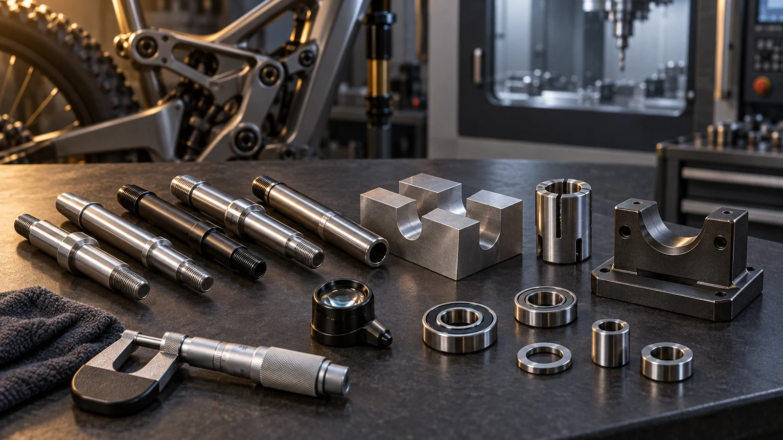
Clamping marks on a pivot bolt should be controlled through permitted contact zones and finished-part requirements, not by asking for soft jaws alone. Identify the bearing or locating surface, any visible finished region and the stock available for gripping during each operation. Then compare contact geometry, restraint and the proposed sequence against those requirements. A small mark can be acceptable on material removed later yet unacceptable on a specified fit surface. Also distinguish local damage from geometry that changes when restraint is released. The acceptance plan should evaluate the required characteristics in the specified condition; a smooth appearance or one roughness reading cannot answer all of them.
Hero: concept illustration of example hardware and its application. It is not a factory photograph, tested component or approved production geometry.
Classify the surface before classifying the mark
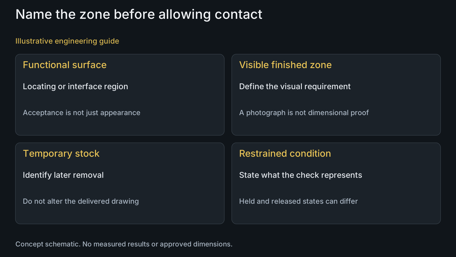
Mark the functional and appearance zones on the drawing or an agreed annotated view. A shoulder supporting an interface, an exposed decorative head and temporary excess stock perform different jobs. Do not reject or accept all contact traces using one cosmetic rule when the part contains several surface functions.
Identify what remains to be machined after each gripping operation. A permitted contact on sacrificial stock is a different proposal from gripping the final locating diameter. Any material allowance or temporary feature must belong to the proposed route; it is not permission to change the delivered component.
Define the final appearance requirement and viewing basis where appearance matters. A reference photograph can explain a visual concern, but it does not establish local indentation depth, roundness or fit. Keep appearance assessment separate from the applicable dimensional and surface requirements.
Soft jaws adapt the contact; they do not prove the result
SCHUNK's soft-top-jaw resource describes jaws that can be machined to a desired clamping diameter. This supports considering an adapted contact shape. It does not establish that any soft jaw, on any pivot, produces a mark-free or distortion-free part.
Ask how the proposed contact matches the actual surface and operation. Include gripping location, supported length, tool access and what changes when the part is transferred. The word soft does not specify the complete contact geometry or replace the machine and workholding manufacturer's requirements.
A collet or dedicated support can be another proposal when appropriate to the geometry. Compare its locating and restraint functions rather than giving the methods a universal ranking. A sleeve-like workpiece and a solid stepped axle may need different treatment even if both have a circular outside profile.
| Proposal | Potentially useful condition | Risk to resolve | Acceptance evidence |
|---|---|---|---|
| Adapted soft jaws | A defined external gripping region | Contact shape or restraint does not suit the actual part | Contact-zone and specified-state feature results |
| Collet or sleeve contact | Suitable circular surface and locating arrangement | Method name conceals actual contact or access limits | Proposed locating and gripping scope |
| Dedicated support | Hollow or sensitive geometry needs another arrangement | Support interferes with required feature or tool approach | Feasibility and affected geometry review |
| Temporary gripping stock | Later removal is part of the intended route | Temporary feature becomes an unauthorized design change | Remaining operations and final drawing conformity |
| Post-finish gripping | A later operation contacts the delivered surface | Appearance-only review misses coating or local damage | Required surface and feature checks after contact |
Restraint and released geometry are different states
A hollow or locally flexible feature deserves attention to the restraint arrangement as well as its surface. SCHUNK's pendulum-jaw information gives a tool-specific example of distributed contact for deformation-sensitive parts. Its configuration and performance are not transferred as a pivot recipe or claimed factory equipment.
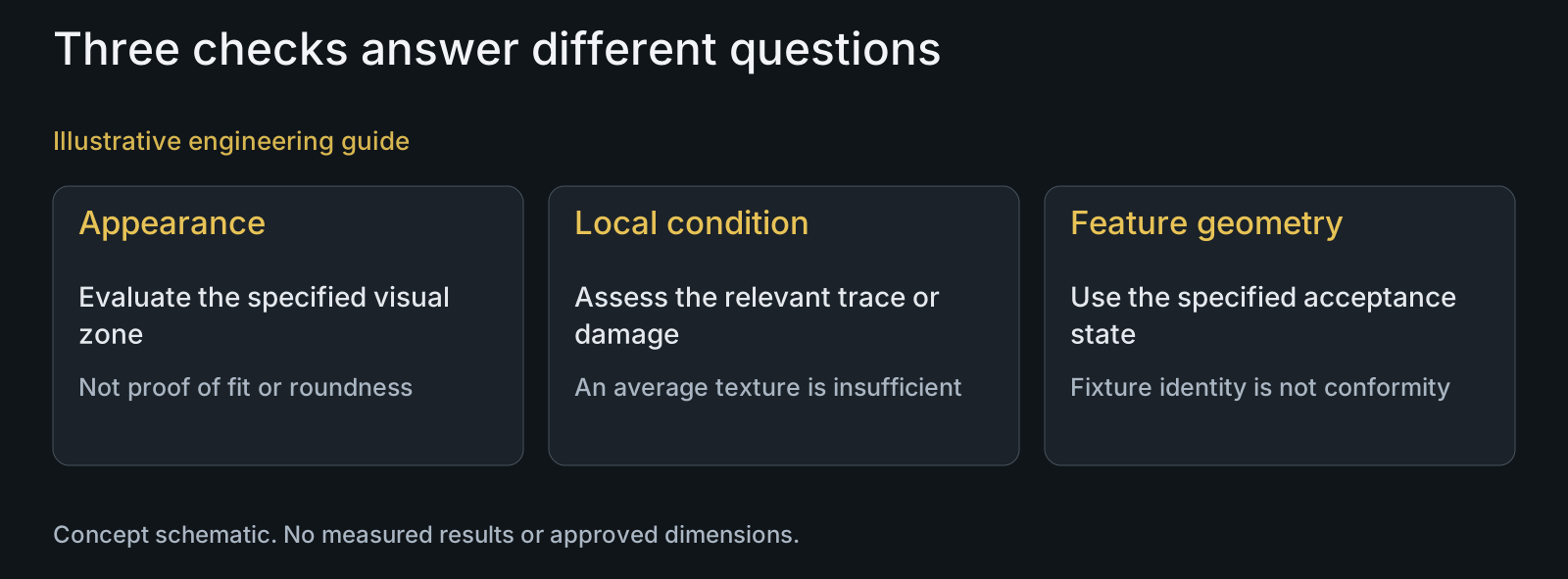
For the component review, identify whether acceptance concerns the released part or another specified restrained condition. Measurements taken during machining can answer process questions without proving the required geometry after removal. Keep the measurement state attached to the result.
Do not reduce gripping force casually to solve a visible mark. Secure restraint and the permitted operation remain essential setup questions for the responsible manufacturing team. Evaluate an appropriate contact or support alternative within that scope rather than treating a lower setting as a universally safe solution.
Roughness cannot replace local-damage acceptance
KEYENCE's surface-height explanation describes Ra as an average profile measure and explains its limits for local extremes and defects. A roughness observation addresses the represented profile and conditions, not every possible mark on the component.
Identify a suspect trace's location and relevant function. A smooth-looking depression or displaced material can require its own assessment even when a separate texture reading is acceptable. The original topic's roughness value is not adopted as a universal PremFixer output limit or a complete no-clamp-damage criterion.
Avoid polishing a mark away without disposition of the affected requirement. Material removal or treatment change can alter a locating surface, transition or supplied finish. A brighter result is not automatically a restored functional part; any rework should preserve the approved final requirements and be assessed accordingly.
A hollow axle requires more than a cosmetic decision
Illustrative engineering example: assume a hollow pivot axle needs a secondary drive feature after its outside locating surface has been machined. One proposal grips that finished outside surface with adapted jaws; another proposes support on a temporary area removed later. No actual clamp mark, dimensional measurement or fixture trial is assumed.
The team first checks which zones may contact the workholding and whether the temporary area can be used without altering the delivered drawing. It then reviews tool access, restraint and the required released geometry. The final outside surface must meet its functional requirements under either proposal; fewer visible traces would not independently establish that geometry.
Select the proposal only after the relevant feasibility and output evidence are available. This example establishes no winning fixture, safe force setting or zero-deformation result. It demonstrates why surface protection and released-part conformity are separate questions in the same workholding decision.
Include surface zones in the manufacturing RFQ
Send the drawing, STEP file, material condition and critical-feature notes with quantities. Show no-grip or appearance zones when required, and identify whether the supplied state includes a later coating. The CNC manufacturing review can then address the actual contact and operation sequence.
Connect the gripping proposal to surface-treatment scope. Contact before treatment and contact on an already treated surface are different route questions. Do not assume that a coating will hide a geometric defect or that all treatment permits the same subsequent restraint.
PremFixer manufactures to the customer's component definition and coordinated supply scope. If a surface constraint requires additional preparation or a dedicated fixture, identify it in the offer rather than silently relaxing the requirement. The feature-tolerance guide helps keep geometry acceptance distinct from the fixture description.
Questions buyers need to confirm
Do soft jaws guarantee no clamping marks on pivot bolts?
No. Review the actual contact shape, gripping region and operation. Assess the required final surfaces and geometry rather than treating the jaw description as an accepted result.
Can a clamp trace be acceptable on one region but not another?
Yes, if the component definition permits it. Temporary stock removed later differs from a finished locating surface or specified appearance zone. Identify location and remaining operations before deciding.
Does an acceptable Ra result prove a clamp indentation is harmless?
No. Ra is an average profile measure, not complete local-damage or geometry acceptance. Assess the relevant trace and feature separately using the specified requirements.
Can gripping force simply be reduced to remove marks?
Do not assume that is an acceptable setup change. The manufacturing team must maintain suitable restraint within the real machine and workholding requirements. Review alternative contact or support and verify affected output.
Should a hollow axle be checked only while clamped?
Use the condition specified for acceptance. An in-process held measurement does not automatically prove released geometry. Identify which state each result represents and check the affected finished requirements.
What should accompany a surface-protection RFQ?
Provide drawings and STEP, material condition, permitted gripping and no-grip zones, functional surfaces, appearance requirements, final treatment and quantities. Identify the secondary operations that may contact already finished surfaces.
Technical references and scope
SCHUNK: Soft top jaws. Public technical description read. Adaptable clamping-diameter concept only; no ownership, tool dimensions or mark-free guarantee transferred.
SCHUNK: Pendulum jaws. Description and options read. Tool-specific distributed contact for deformation-sensitive workpieces; no point-count recipe or universal pivot performance adopted.
KEYENCE: Surface height from Ra to Rz. Ra definition and limitations section read. Average versus local defect distinction only; page's standards references, Rz rules and instrument claims not adopted.
Explore related component, material and sourcing decisions in the customer decision knowledge center. For a drawing review, use the Drawing/BOM RFQ path.
Define permitted contact for your pivot manufacturing route
Send the drawing, STEP file, material condition and annotated functional or appearance zones, with the intended finish and quantities. PremFixer will review suitable manufacturing scope and the checks needed for surfaces and geometry affected by workholding; no universal mark-free fixture or roughness limit is assumed.
Discuss the drawing and BOM