
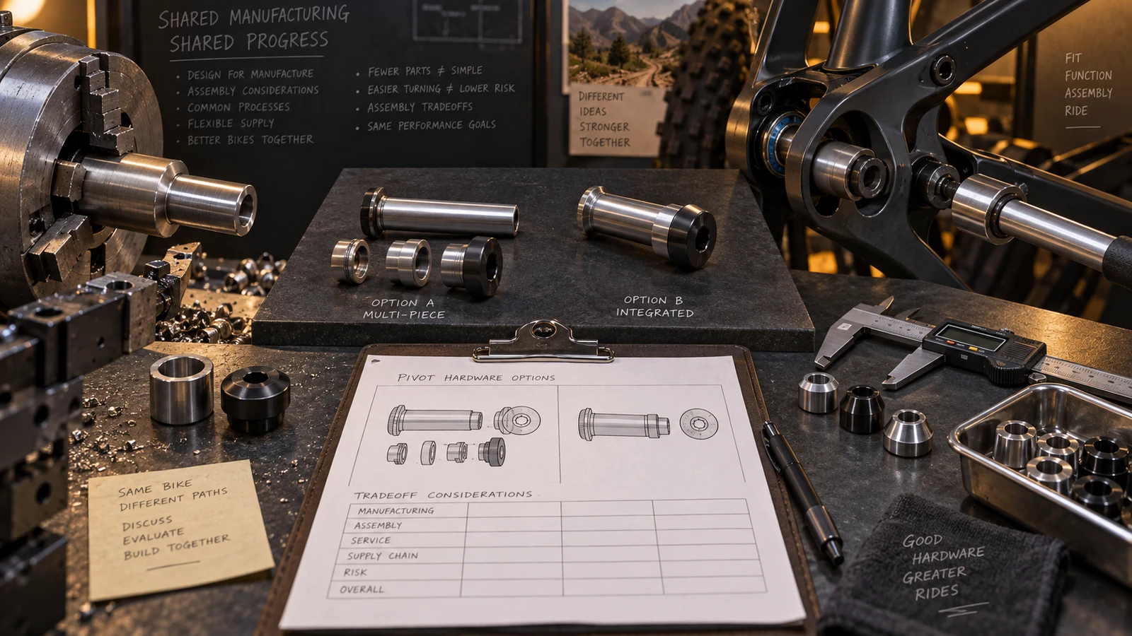
DFM asks how pivot hardware can be manufactured; DFA asks how its components can be handled, oriented and assembled. An OEM considering design optimization should compare both against the same bearing, spacer, receiver and service requirements. Fewer pieces or a simpler machining operation can be useful, but they may move difficulty into insertion, tool access or replacement. Identify the proposed feature, the manufacturing effect and the complete assembly consequence before selecting an alternative. Keep functional constraints explicit and make the accepted outcome one coherent drawing, BOM and assembly definition. No automatic part-count reduction, cost saving or design approval is promised.
Hero: concept illustration of example hardware and its application. It is not a factory photograph, tested component or approved production geometry.
Define the complete alternative, not an isolated saving
Identify the manufacturing difficulty and assembly difficulty separately. Tool access, holding and feature creation differ from part orientation, insertion and counterholding. A recommendation should name which problem it addresses and what it changes in the neighboring components.
The drawing-level DFM guide examines engagement, transitions, tolerances, material and finishing. This guide adds the assembly consequence to each candidate, so a useful manufacturing proposal is not mistaken for acceptance of a revised kit.
Keep the functional requirements as the common comparison basis. Do not loosen a seat requirement merely to make a candidate easier to produce, or remove a separable item before understanding its contact and maintenance role. The responsible design team decides which constraints can change.
Ask why a component is separate before combining it
Boothroyd Dewhurst's DFA explanation examines relative motion, functional material differences and assembly/disassembly needs when identifying consolidation candidates. It also retains manufacturing feasibility as a separate question. Its general saving claims are not treated as project results for bicycle pivots.
Apply that reasoning to an actual spacer, cap or retaining item. Explain whether separation supports a moving relationship, a different required material, access or replacement. Not every separate part is waste, and not every integrated feature is feasible on the specified route.
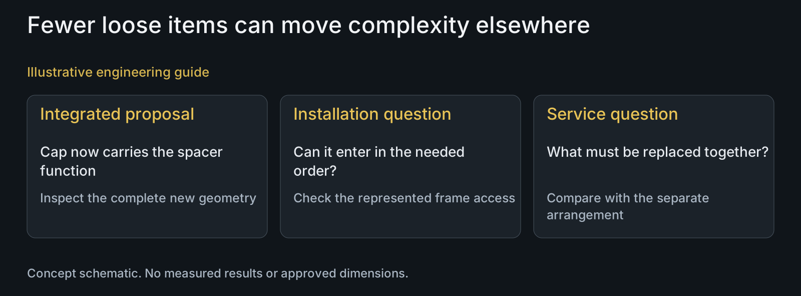
A consolidated cap-and-spacer proposal can change what must be handled during installation and what is replaced during service. Compare those effects with the original arrangement. Do not advertise consolidation as a reliability improvement without the applicable design and evaluation basis.
| Proposed change | Manufacturing question | Assembly or service tradeoff | Functional review |
|---|---|---|---|
| Integrated cap and spacer | Can the complete shape be held and reached? | Different insertion order or replacement scope | Required contacts and separability |
| Added entry chamfer | Is the feature practical on the route? | May ease insertion or reduce usable contact | Final seating and full-thread relationship |
| Asymmetric orientation feature | How is it made and inspected? | May prevent a defined wrong arrangement | Actual mating exclusion, not appearance |
| Changed drive or head | What tooling and geometry change? | Different access or counterholding need | Head seat and represented tool envelope |
| Reduced tolerance complexity | Can noncritical controls be simplified? | Mating relationship may still be sensitive | Function-specific stack and fit basis |
| Retained separate component | Is manufacture simpler or more repeatable? | More handling but possible service benefit | Why separation is required or useful |
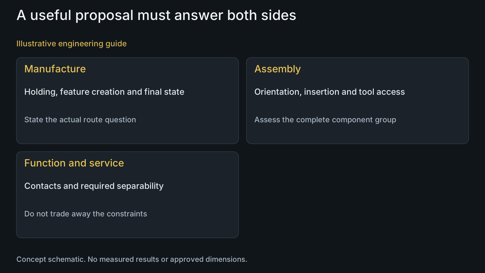
Review entry geometry, orientation and access together
Locate insertion direction and the surfaces that must align before tightening. A lead-in can assist entry while also changing a contact envelope or available full thread. Specify its purpose and relation to the final seated state rather than adding a generic chamfer everywhere.
Distinguish a feature that prevents an incorrect orientation from one that merely makes orientation easier to see. A mark cannot physically prevent reversal; an asymmetric feature must actually exclude the unwanted arrangement in the represented mates. Neither should be called error-proofing without that basis.
Check the drive tool and required counterhold with the assembled frame geometry. A head that is easy to machine can still be difficult to reach, and an integrated item may need a different assembly order. Review production installation and intended service access separately.
Compare manufacturing routes without moving hidden costs
For each candidate, ask how the complete geometry is held and reached through the proposed CNC-turning review. Keep route-specific feasibility and tooling questions distinct from the desired part shape. No universal tool-reach limit is assigned here.
Compare the relevant material condition, final surface and inspection requirements across the alternatives. An integrated component can reduce separate handling but introduce a harder-to-measure relationship or require different preparation. Simplification must be assessed at the supplied kit level, not only at one machining operation.
Request quotation scope for the actual alternative and quantity mix. Include any moved mating-item, packing or sample work. A lower individual part price does not settle complete assembly cost, and a more complex part is not necessarily worse if it supports the defined overall requirement.
Make the selected configuration consistent across its documents
Show the accepted and rejected proposals with their reasons. Update the affected part definition, kit quantities, orientation and assembly sequence together. A changed part drawing paired with an old BOM can leave a deleted spacer still ordered or an integrated function omitted.
Connect inspection to the final requirements of the chosen geometry. A dimensional feature that disappeared may no longer need its earlier check, while a new integrated relationship may need a different assessment. Do not carry obsolete inspection solely because it belonged to the previous part count.
Use prototype review to address the remaining manufacturing and assembly questions in the selected state. Identify what the prototype represents. One visually assembled sample is not automatic confirmation of production feasibility, installation consistency or application performance.
Review example: merging a spacer changes installation order
Illustrative engineering example: assume a pivot uses a separate cap and spacer, and a proposal integrates the spacer function into the cap. The buyer expects fewer loose items at assembly. No actual dimensions, handling times or cost saving are supplied.
The reviewer checks whether the integrated form can reach its intended contact after the bearing and frame members are positioned. They compare manufacturing access, insertion order and the replacement scope if one functional region becomes unsuitable. The reduced loose-part count does not answer those questions.
If the alternative remains useful, its complete definition and assembly sequence become the comparison subject. If access conflicts with the fixed interfaces, retaining separate items can be justified. The example does not declare a winning design; it makes the proposed simplification's consequences visible.
Questions buyers need to confirm
What is the difference between DFM and DFA for pivots?
DFM examines manufacture, while DFA examines component handling and assembly. Compare both with the same functional interfaces. A machining improvement that creates inaccessible installation or wrong contact geometry is not a complete optimization.
Is the design with fewer parts always better?
No. Determine why items are separate, including motion, material needs, assembly access and service. Then assess manufacturing feasibility and the complete alternative. A part-count reduction alone cannot establish cost, fit or reliability benefit.
Can a visible mark prevent reverse assembly?
It can identify orientation but does not physically prevent reversal. If prevention is required, evaluate an appropriate feature against the actual mates and unwanted arrangement. Do not call a helpful mark an established exclusion mechanism.
Should every insertion edge get a larger chamfer?
No. Define the entry purpose and compare the change with usable thread, contact and final seating. An easier insertion does not justify reducing a functional surface without the responsible design review.
What should a shared review produce?
Produce coherent proposed changes, reasons, constraints and unresolved questions. For the accepted alternative, align drawings, BOM, assembly sequence and inspection. Separate departmental suggestions should not leave conflicting supplied-part definitions.
What makes a DFM/DFA RFQ actionable?
Send part and assembly drawings, STEP, mate details, material and finish requirements, tool-access views and quantity mix. Identify the manufacturing or assembly difficulty and any proposed alternative, with prototype questions and design authority explicit.
Technical references and scope
Boothroyd Dewhurst: part consolidation and DFA criteria. Relative-motion, material and assembly/disassembly questions for consolidation candidates, with manufacturing feasibility retained. General saving figures and illustrative results are not adopted.
Explore related component, material and sourcing decisions in the customer decision knowledge center. For a drawing review, use the Drawing/BOM RFQ path.
Compare the complete pivot design alternatives
Share the drawings and STEP, bearing and spacer interfaces, BOM, installation access, service needs and proposed changes through the Drawing/BOM RFQ path. PremFixer can review route feasibility and component definition while your team evaluates assembly consequences and accepts the design.
Discuss the drawing and BOM