
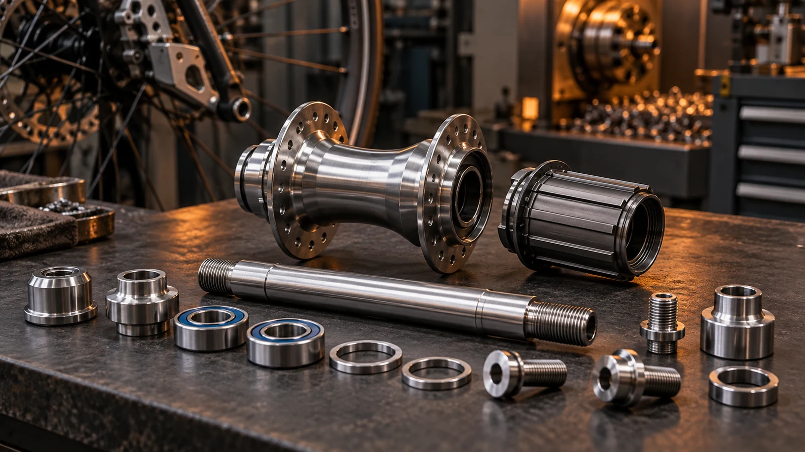
Stainless hub axle bolts need their own component definition; a frame pivot specification cannot be transferred because the parts look alike. First identify whether the ordered part is an axle, an end-retention fastener, a bearing-adjustment element or wheel-mounting hardware. Then show what rotates, what remains located and which contacts carry clamping or operating loads. Wheel rotation alone does not prove that every nearby bolt has the same fatigue duty. Material, thread manufacture and any surface treatment must address the actual part and assembly. Do not replace model-specific installation requirements with a generic stainless rule or treat nominal diameter as evidence of compatibility.
Hero: concept illustration of example hardware and its application. It is not a factory photograph, tested component or approved production geometry.
Name the hub component before assigning a load case
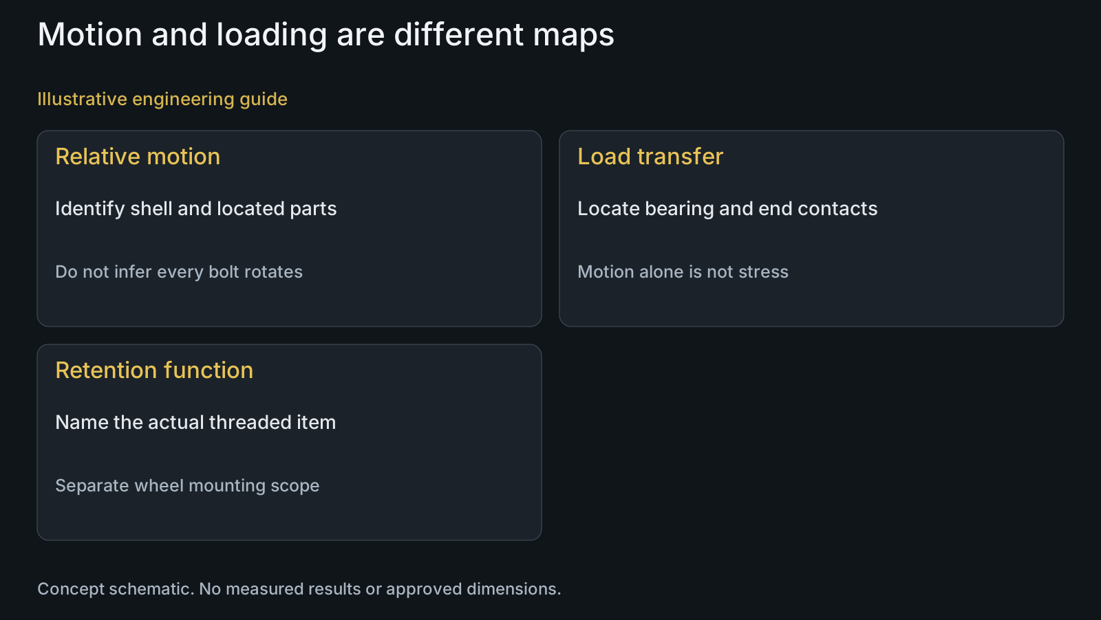
The expression hub bolt can refer to different items. Use a section or exploded assembly to identify the hub shell, bearings, axle, end caps and any actual threaded retention parts. Show the ordered item's position and part number rather than asking a supplier to infer its function from a photograph.
Mark relative motion separately from the load path. In a hub architecture where the shell turns relative to a located axle, the rotating shell and an end fastener do not have identical motion. That observation is not a complete stress analysis: load direction and magnitude can still vary at a non-rotating component. Describe both rather than equating rotation with every fatigue requirement.
Wheel-mounting hardware is another scope. The pivot bolt versus thru-axle guide addresses that distinction. This article focuses on defining hardware within the hub and its retention/bearing interfaces, not declaring a suspension bolt interchangeable with a wheel axle.
Locate bearing contacts and the installed clamp path
Identify where each bearing ring locates, which shoulders establish axial position and how the end hardware contacts the axle or other parts. A part that retains an end component may serve a different task from a separate bearing adjustment. Do not assume that tightening either item produces the same bearing condition.
DT Swiss explains that its hub bearing arrangement accounts for clamping from the wheel mounting system and distinguishes behavior before and after installation. This is a manufacturer-specific design example, not a procedure to copy into all hubs. It demonstrates why a free-rotation observation on a bench should be interpreted within the relevant installed configuration.
Supply the actual assembly instruction and bearing/interface definition for the ordered hub revision. If drag appears only after wheel installation, preserve that observation. It can direct review toward installed contacts and loading rather than an immediate change in stainless grade or an improvised loosening adjustment.
| Part or function | Decision input | Incorrect transfer assumption | Useful verification |
|---|---|---|---|
| Hub shell and bearings | Relative motion and ring location | Every nearby fastener rotates with the shell | Actual assembly motion/contact map |
| Located axle | Support and operating load path | A pivot bolt duty automatically applies | Axle geometry and specified loading |
| End-retention fastener | Seat, engagement and bottom clearance | Same thread means interchangeable hardware | Final contact and receiver definition |
| Bearing-adjustment element | Its specific adjustment function | Retention torque equals bearing adjustment | Model-specific assembly instruction |
| Wheel mounting interface | Installed clamp path | Bench behavior represents every installed state | Review the released installed configuration |
Choose material and thread processes for the actual requirement
304 is an alloy designation, not a complete hub hardware strength or durability specification. State the finished material condition, required properties and relevant exposure alongside the drawing. An end-retention fastener and an axle section may have different geometry and inspection needs even within one BOM.
Rolled threads or shot peening should not be specified solely because the application is a hub. If either process is proposed for a fatigue-related requirement, define the relevant feature, final condition and evaluation basis. A process name does not establish a universal life improvement or the suitability of every part in the assembly.
Keep the mating thread and effective engagement visible. A change intended to help one feature may affect the receiver, final fit or the shoulder transition. Use the custom-thread input guide to define the interface rather than extending a pivot rule to unknown hub geometry.
Describe the observed failure without jumping to a material cause
Bearing drag, loosened retention, damaged contact surfaces and a fractured fastener are different observations. Record the affected part and installed condition. A wheel that is difficult to turn does not by itself show that a stainless bolt has inadequate strength.
For a crack or fracture, retain the failed part and its order/process history. Relevant review can include geometry transitions, mating support, installation and loading, but those are investigation inputs rather than a diagnosis from the application name. Do not automatically label the event rotating fatigue because the wheel rotates.
For a repeat-order change, compare the end contacts and supplied revision as well as the bolt. A different end cap, spacer or bearing arrangement can change how an unchanged fastener functions. Keep those changes in the inquiry rather than presenting the bolt as the only possible source of the symptom.
Illustrative review: the same thread, a different end contact
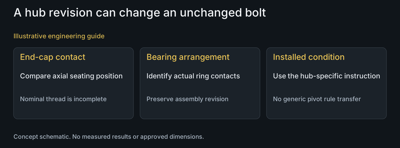
Illustrative engineering example: assume an OEM replaces one hub end-cap design while retaining the same nominal retention thread. The new cap has a different axial contact position. No dimension, test result or existing fault is assumed.
The reviewer checks whether the cap reaches its intended seat, whether the bolt can bottom out and whether the changed contact alters the defined bearing/axle stack. Matching thread diameter is only one input. The old hardware's appearance and the successful thread entry do not approve the revised assembly.
The useful output is a comparison of the changed contacts and an identified evaluation scope for the installed configuration. A generic upgrade to another alloy or a thread process would not answer the axial-contact question. This example is engineering analysis, not a claim about an actual customer hub.
Questions buyers need to confirm
Are hub bolts and frame pivot bolts specified in the same way?
Compare their actual roles first. Identify the ordered component, bearing/receiver contacts and installation requirements. Similar appearance or thread size does not establish shared loading or compatibility.
Does a rotating wheel mean the hub axle bolt also rotates?
Not necessarily. Map component motion in the actual hub. Then assess loading separately: a located component can still experience varying forces, so neither motion nor its absence is a complete fatigue definition.
Is 304 stainless enough information to quote hub hardware?
No. Provide the finished material condition, required properties, component geometry, supplied finish and assembly role. The alloy name does not define the end contact, engagement or application acceptance.
Should every hub bolt have rolled threads and shot peening?
Do not prescribe those processes from the hub label alone. Define the feature, final requirements and evidence scope if they are proposed. No universal fatigue improvement or process suitability is established here.
Can bearing drag be evaluated only with the wheel removed?
Use the relevant manufacturer's assessment method and installed configuration. A hub design can account for wheel-mounting clamp effects; a bench observation alone may not represent its intended installed behavior.
What should a stainless hub hardware RFQ include?
Send the hub assembly section, ordered part drawings, bearing/end-cap interfaces, receiver and material requirements, BOM revision and installation scope. Identify any proposed change or observed symptom so manufacturing review addresses the right component.
Technical references and scope
DT Swiss: Bearing technology. Manufacturer-specific example of installed clamp effects; no universal hub adjustment procedure or claimed DT Swiss compatibility.
Explore related component, material and sourcing decisions in the customer decision knowledge center. For a drawing review, use the Drawing/BOM RFQ path.
Define the hub interface before transferring a hardware rule
Send the hub and ordered hardware drawings, STEP models, bearing/end-cap BOM, material condition and relevant assembly or evaluation requirements. PremFixer can review the manufacturable component and inspection scope without assuming universal hub or frame compatibility.
Discuss the drawing and BOM