
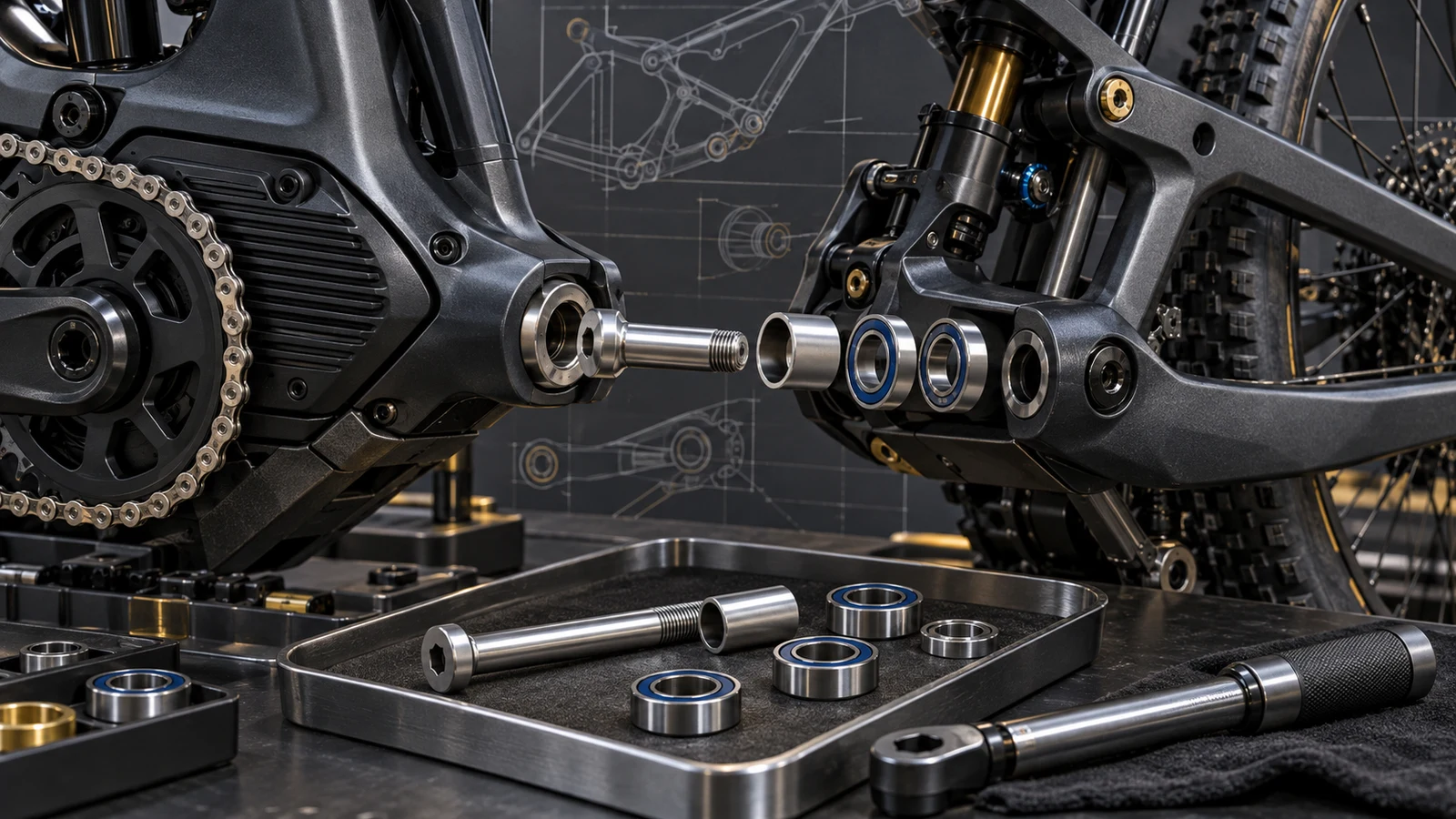
Titanium pivot hardware can be evaluated for an e-MTB, but a high motor-torque rating and the TC4 material name do not show that a particular pivot is strong enough. The designer must translate bicycle inputs into the actual joint demands, including load direction, support span, receiver geometry and initial assembly. Installation torque is a separate quantity from motor output, and neither is a direct bolt-stress value. For an OEM considering a titanium proposal, state the failure mode behind each margin and the configuration represented by each test. No universal pivot force, safety factor, riding-life guarantee or retrofit permission follows from the e-MTB category alone.
Hero: concept illustration of example hardware and its application. It is not a factory photograph, tested component or approved production geometry.
Keep motor output and installation torque separate
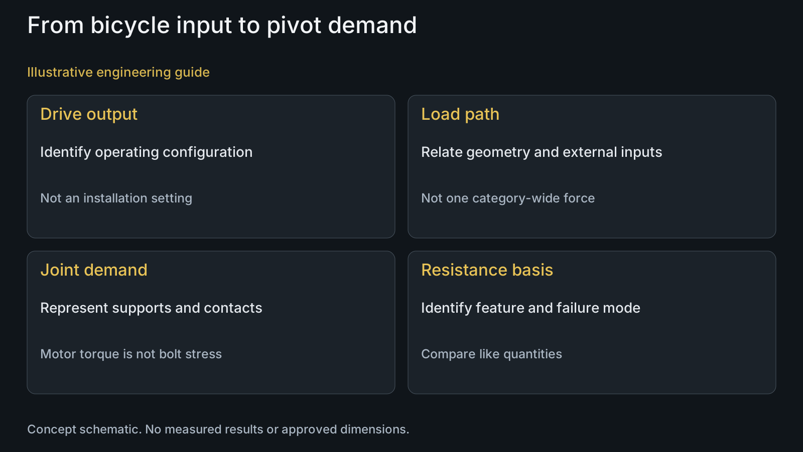
A drive-unit rating describes an output condition, not the wrench setting for a suspension bolt. Bosch's performance-upgrade announcement also shows that available output settings have bicycle-manufacturer limits and operating context. That source does not provide a force or allowable for your pivot. Identify the actual system and intended operating conditions rather than using one marketing maximum as the complete load case.
Installation torque helps establish a specified assembled condition through the relevant friction and contact arrangement. It is not the drive-unit output transmitted unchanged through every fastener. The torque and clamp-force guide explains why a wrench value cannot by itself identify the internal clamp force in every surface condition.
As a simplified engineering relationship, a tangential force producing torque T at effective radius r is T divided by r. This is not a complete drivetrain or suspension calculation. It illustrates why a torque number needs geometry before it can even describe a force, and why that force still needs a load-path model before it becomes a pivot demand.
Translate the relevant bicycle loads into the supported joint
Identify the specific pivot and its connection to the linkage, frame and adjacent components. Draw the relevant load path and locate bearing support, sleeve contacts and the receiving thread. The component may carry different combinations of clamp-related, transverse and bending demands; the assembly drawing is needed to establish the actual arrangement.
Document the intended operating cases, including which external inputs act together and which represent different conditions. Rider contribution, drivetrain reactions, suspension motion, braking and impact-related cases should not be replaced by an unexplained single force. The responsible design model must justify how each applicable input reaches the joint.
NASA's Fastener Design Manual treats preload and external loading as related but distinct in a clamped-joint model. That supports the general need to represent the joint, not a NASA qualification for a bicycle. State support assumptions and contact behavior rather than assuming that a bare bolt is loaded exactly like the assembled pivot.
| Input or assessment | What it describes | Insufficient shortcut | Required connection |
|---|---|---|---|
| Drive-unit torque | Output under identified operating conditions | Use it as installation torque or direct bolt stress | Drivetrain geometry and the applicable bicycle load path |
| Installation instruction | The represented initial assembly condition | Treat a wrench value as every internal load | Named contacts, products, mating hardware and procedure |
| Joint load case | Demand with stated direction and support assumptions | Apply one generic e-MTB pivot force | Identify the actual linkage, receiver, sleeve and support |
| Static bolt margin | Defined demand versus a relevant resistance basis | Assume receiver, contact and fatigue approval | State feature, failure mode, material condition and assumptions |
| Component test | The represented specimen and fixture | Call every platform or material swap validated | Establish the relationship to the actual supported joint |
| Repeated-loading assessment | Specified loading and observed endpoint | Convert runout into unlimited riding life | Preserve configuration, exposure and relevant failure definition |
State what each strength margin actually compares
A material stress value and an applied force cannot be divided directly to create a meaningful factor. Translate the load case into the relevant demand using geometry and justified assumptions, then compare like quantities with the appropriate resistance basis. A margin must identify whether it concerns yield, ultimate failure, fatigue or another defined limit.
Check the actual feature and component that could govern. A bolt-yield assessment does not establish receiver-thread resistance, local contact acceptance, sleeve support or bearing-stack function. Stronger stock cannot correct an unsupported shoulder, an incorrectly located thread runout or an incompatible clamping arrangement.
Define the specified titanium condition and source of the resistance data. TIMET's 6-4 sheet presents properties tied to material condition and product context, not one universal TC4 value for every finished pivot. Keep reference stock data separate from application allowables and finished-part acceptance. No numerical design margin is calculated here.
Represent the assembly in the validation question
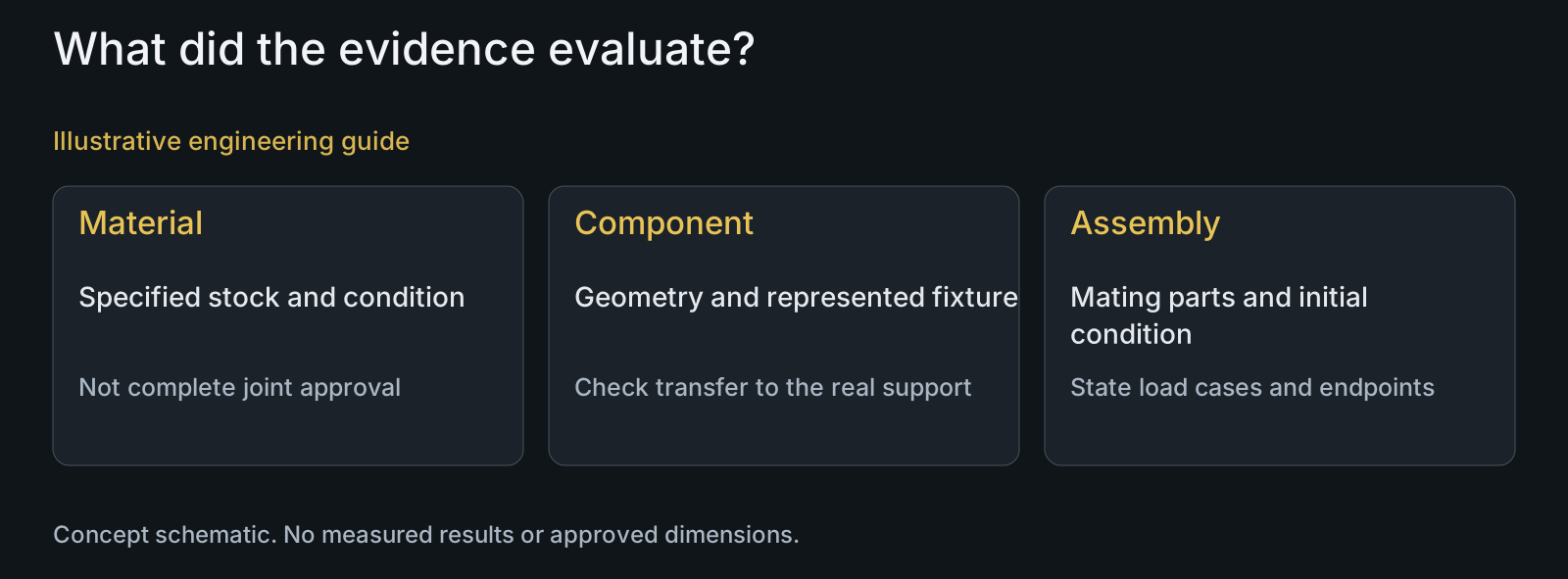
Decide which question each assessment answers: material identity, finished dimensions, assembly function or durability under represented loading. A material report can support its stated stock scope without establishing bearing-stack behavior. A component test can address its represented fixture without reproducing every frame receiver and support arrangement.
Model-specific instructions demonstrate why assembly is not a category-wide detail. Yeti's MY23 160E manual identifies different hardware and preparation conditions within one frame. It is cited as a bounded documentary example, not a current installation instruction for another model or approval for titanium substitution.
A proposed material or surface change should be reviewed with the represented mating parts, initial assembly and relevant test endpoints. Keep static and repeated-loading questions distinct. The titanium fatigue-evidence discussion explains why surviving a stated observation does not establish unlimited durability or a universal riding interval.
Illustrative review: unchanged motor torque does not mean unchanged pivot demand
Illustrative engineering example: assume two proposed e-MTB configurations share a drive-unit torque setting but differ in effective chainring radius and in the support span of one pivot. A designer is considering titanium hardware for the second configuration. No load calculation or physical test has been performed.
The simplified torque-radius relationship indicates that the same torque need not correspond to the same tangential force. The changed suspension support geometry then prevents direct transfer of the first configuration's internal bolt demands. The review must establish the second load path before comparing material resistance or claiming an unchanged margin.
The team identifies the needed component and assembly inputs and separates manufacturability from application approval. PremFixer's full-suspension solution discussion can support a drawing-defined hardware scope; it does not approve an untested substitution. This assumed example supplies no actual force, calculated safety factor, FEA result, passed test or customer performance claim.
Questions buyers need to confirm
Are TC4 titanium pivots automatically strong enough for every e-MTB?
No. Identify the actual material condition, finished geometry, support, receiver and loading. The material name and bicycle category do not supply a complete resistance or durability assessment.
Is motor torque the torque used to install the pivot bolt?
No. Drive output and assembly tightening are different quantities. Follow the actual component's approved assembly conditions rather than transferring a motor specification to a wrench setting.
Can a generic pivot force establish a universal safety factor?
No. A force needs a justified load path and geometry to determine the relevant demand. State the failure mode and resistance basis; a material stress value divided by a force is not a valid factor.
Does a favorable bolt-yield margin approve the complete pivot?
No. Receiver threads, contacts, sleeve support, bearing-stack function and repeated loading may raise different questions. Assess the applicable limits instead of extending one favorable comparison to the entire joint.
Can a similar-looking titanium bolt replace original frame hardware?
Not from appearance or nominal thread size alone. Confirm the controlled interface, material condition, surface and assembly requirements for the actual revision. Application approval remains with the responsible product team.
What information starts an e-MTB titanium pivot review?
Provide the component and assembly drawings, joint location, mating BOM, support geometry and intended operating cases. Identify material and surface state, installation conditions and the validation question, including any actual load or test records and their scope.
Technical references and scope
Bosch: Dynamic drive-unit performance upgrade announcement. Operating and bicycle-manufacturer context of drive-unit settings. No numeric output rating, pivot force, installation value or compatibility transferred.
NASA: Fastener Design Manual, RP-1228. General clamped-joint distinction between preload and external loading. Not a bicycle standard, design prescription or PremFixer validation.
TIMET: TIMETAL 6-4 data sheet. Material-condition and product context for reference properties. No universal 880 MPa value or finished-pivot allowable adopted.
Yeti Cycles: MY23 160E owner's manual. Model-specific hardware preparation illustrates assembly context. No torque, product application, titanium substitution or current cross-model maintenance instruction reproduced.
Explore related component, material and sourcing decisions in the customer decision knowledge center. For a drawing review, use the Drawing/BOM RFQ path.
Connect titanium hardware to the actual e-MTB joint
Send controlled drawings or STEP models, the mating BOM, support and receiver details, specified titanium condition and assembly requirements. Include the relevant load cases and validation scope if available. PremFixer will review manufacturing and sample supply; the responsible OEM retains load-model, system-validation and application-approval decisions.
Discuss the drawing and BOM