
Form tapping is not automatically a stronger choice for a stainless pivot axle's internal receiving thread. It displaces material rather than removing cutting chips, so the material condition and prepared hole must suit that operation. Cutting taps present a different chip-management task. For an OEM choosing between the routes, compare the actual alloy state, pilot-hole definition, tool reach, lubrication and required complete thread length. Then specify how the delivered thread and assembly interface will be accepted. A chip-free tapping operation does not prove a fixed strength improvement, eliminate every cleanliness requirement or establish that a mating bolt will seat correctly in the pivot stack.
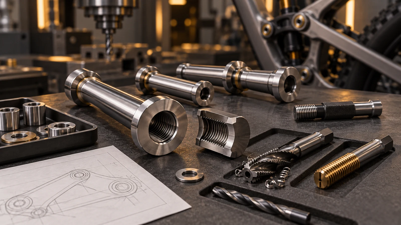
Hero: concept illustration of example hardware and its application. It is not a factory photograph, tested component or approved production geometry.
Cutting and forming create different preparation tasks
OSG's forming-tap explanation describes thread production by plastic deformation without cutting chips. This is a mechanism distinction, not a statement that every stainless grade or every hole suits that listed tool.
For cutting taps, chip movement is part of the route. OSG's stainless spiral-flute guidance specifically identifies difficult chip evacuation and entanglement in stainless applications. Tool geometry and access therefore matter alongside the nominal thread designation.
Distinguish these internal-hole operations from external thread rolling on a bolt. The tools, starting geometry and inspected member are different. An external-thread comparison cannot be copied into a hollow receiving axle simply because both routes involve forming material.
The alloy label does not approve form tapping
Sandvik Coromant's tapping discussion explains that forming requires material flow and a different prepared-hole size from cut tapping. The session's application examples concern automotive aluminium, not a validated stainless bicycle component.
Identify the specified stainless grade and condition before selecting an applicable tool and process. A material-family label does not establish the current stock condition or the suitability of a particular forming tool. Resolve that question with the relevant tool guidance and actual component definition.
Treat a proposed process change as a new route comparison. Keep the finished thread requirement fixed while reviewing what must change upstream. Do not transfer a claimed strength gain from another material, specimen or tool demonstration to this receiver without component-relevant evidence.
| Decision | Cut-tapping consideration | Form-tapping consideration | Evidence needed |
|---|---|---|---|
| Material condition | Applicable cutting tool and chip behavior | Material flow and applicable forming tool | Specified alloy state and tool guidance |
| Prepared hole | Hole suited to the cutting route | Different hole preparation may be required | Finished thread limits and route-specific hole definition |
| Blind-hole space | Chip path and tool lead must fit | Chip-free operation still needs tool space | Complete thread length, lead space and bottom clearance |
| Supplied cleanliness | Cutting chips and residues must be addressed | Earlier-operation debris and residues remain relevant | Defined cleaning and supplied-state requirement |
| Performance claim | Process label is not a strength result | Forming is not an automatic percentage gain | Actual member, engagement and appropriate comparison |
A pilot-hole change can affect more than the tapping operation
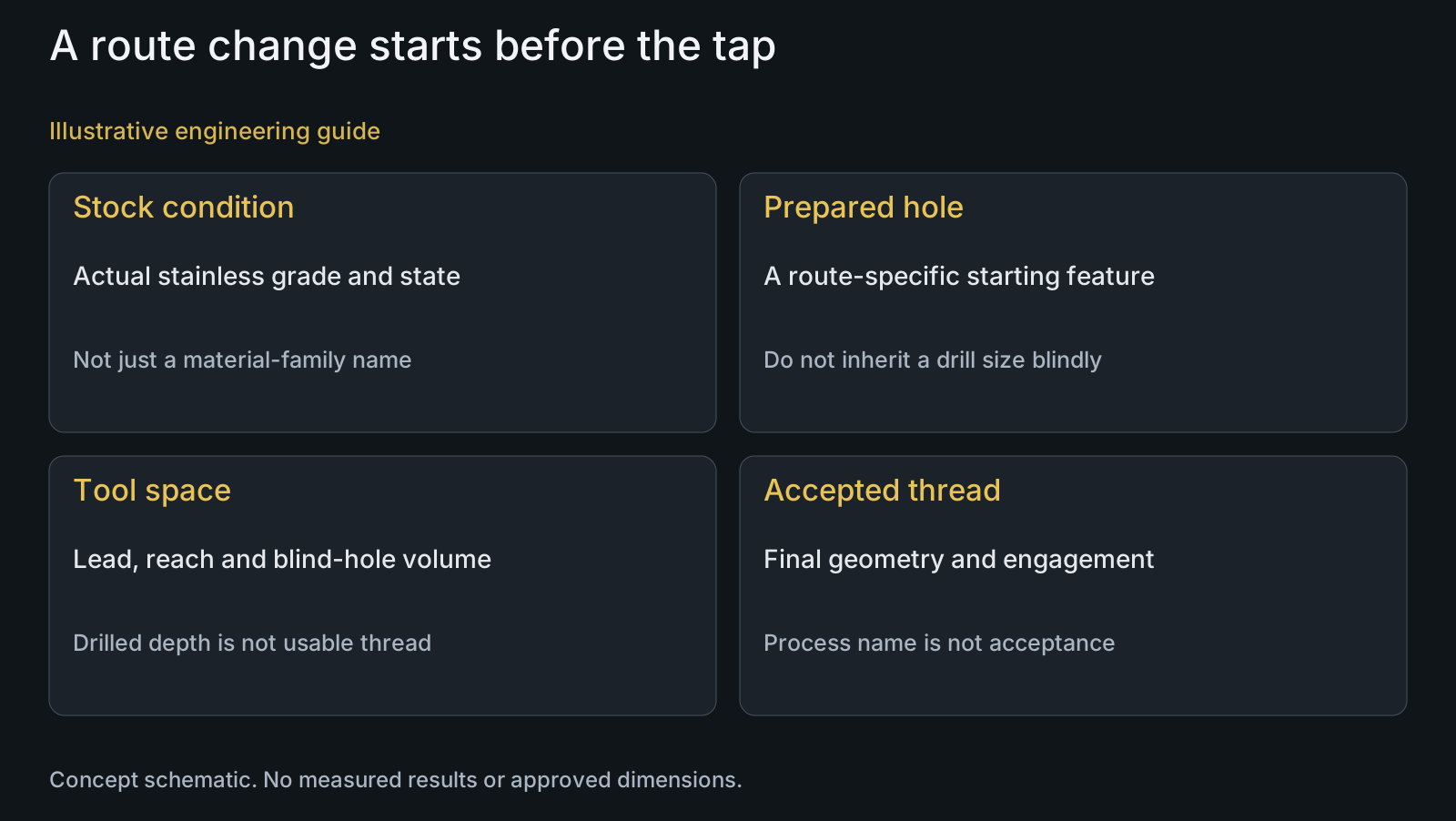
Do not retain an existing cutting-tap drill size by habit when evaluating a forming route. Use the applicable tool and thread requirements to establish the prepared-hole specification. The customer drawing must remain clear about the accepted finished feature rather than accidentally prescribing an incompatible process intermediate.
As engineering analysis, a receiver with a narrow surrounding section requires review of the actual hole and remaining geometry before route approval. Compare the inside feature with adjacent outside diameters and transitions. No generic minimum wall thickness or forming-load allowance is established here.
For a blind hole, distinguish drilled depth, tool-entry and lead space, complete thread length and bottom clearance. A deep drilled cavity does not automatically provide the same usable engagement. Keep the mating bolt's installed position separate from the tap's available travel.
Chip-free is not the same as ready to assemble
A forming operation avoids producing cutting chips in that operation. It does not make the preceding drilling debris, fluid residues or later handling disappear. Define the required supplied cleanliness separately instead of describing a chip-free thread as automatically clean.
Lubrication and tool access need review for the selected tool and material. State the relevant process and subsequent surface-treatment sequence without prescribing an unverified universal lubricant, concentration or speed. Residue removal and the delivered condition belong in that sequence.
The stainless deburring comparison addresses a different edge-removal decision. Do not use either forming or deburring as a substitute for identifying the protected internal thread and its accepted final geometry.
Acceptance must distinguish thread fit from usable engagement
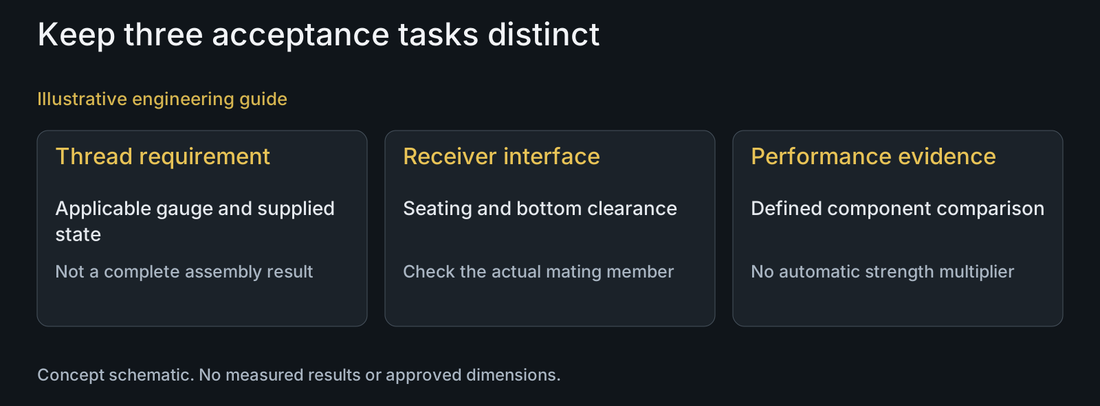
A defined thread gauge check addresses its applicable thread requirement. It does not approve the whole pivot stack, usable engagement, shoulder seating or blind-hole bottom clearance. Identify the thread system, size, pitch and internal class along with the relevant acceptance method.
If finished profile detail is part of the comparison, identify an appropriate additional assessment rather than infer it from a process name. Any sectioned sample would be a separately defined inspection activity, not a standard deliverable promised for every order.
Keep the delivered state visible when subsequent finishing or pre-applied products are involved. A machining-stage result does not necessarily represent every later condition. The effective engagement guide addresses which complete threads actually participate in the assembled connection.
Compare two routes without assuming either has won
Illustrative engineering example: assume a stainless receiving axle currently has a cut-tapped blind hole. An OEM proposes form tapping to avoid chip-management difficulties, but its drawing combines a finished thread callout with the original pilot-hole instruction.
The review separates that process intermediate from the finished acceptance task. It checks the alloy condition, proposed prepared hole, surrounding section and available tool space. The required complete thread length and mating bolt bottom clearance remain unchanged unless the designer approves a revision.
A route can then be evaluated against both manufacturing feasibility and final thread acceptance. No measured strength advantage, tap life, scrap reduction or approved supplier process is assumed. The example shows why changing only the tool name is not a complete conversion.
Request a receiver-specific manufacturing review
Send the receiver drawing and STEP to the CNC turning review, together with the mating bolt, alloy condition, hole type, complete thread length, finish and quantities. Mark any process instructions that may be intended as historical rather than mandatory.
Connect later processing to the supplied surface scope. The thread-class guide helps distinguish an internal-thread designation from an external one; neither class notation establishes material strength.
PremFixer reviews the requested component and agreed manufacturing scope. The availability and validation of a particular internal-thread route require project confirmation; this comparison does not claim an installed forming-tap line, universal inspection package or automatic performance gain.
Questions buyers need to confirm
Does form tapping guarantee stronger stainless pivot threads?
No. A percentage gain needs evidence for the actual alloy condition, receiver and engagement. Plastic deformation describes the route; it does not establish a universal strength result.
Can the existing pilot-hole instruction stay unchanged?
Do not assume so. Review it against the proposed forming tool and finished thread limits. Separate a mandatory drawing feature from a historical process intermediate before approving a change.
Does a blind hole favor forming in every case?
No. Removing the cutting-chip task does not resolve material suitability, tool lead, reach, lubrication or available complete thread length. Evaluate those fields and the mating bolt's bottom clearance.
Does chip-free tapping eliminate cleaning?
No. Drilling debris, process-fluid residues and subsequent handling remain relevant. Specify the accepted supplied cleanliness independently of whether the tapping operation generates cutting chips.
Does a thread gauge pass prove adequate pivot engagement?
No. Keep usable complete threads, installed member position, shoulder contact and bottom clearance separate from the defined gauge check. Provide both mating parts and the final supplied condition.
What should an internal tapping RFQ include?
Send receiver and mating bolt drawings, STEP, stainless grade and condition, hole type, complete thread length, bottom clearance, finish and quantity. Identify fixed process instructions and the requested final acceptance scope.
Technical references and scope
OSG: A-XPF forming-tap mechanism. Complete mechanism and relevant application text read. Plastic displacement and no cutting chips only; listed applications do not establish suitability for this stainless component.
OSG: A-SFT-SUS stainless chip management. Full relevant mechanism/features text read. Stainless cutting-chip evacuation concerns only, no proprietary tool performance promises transferred.
Sandvik Coromant: Solid Round Tools session9. Full transcript read. General material-flow suitability and different prepared hole; aluminium-specific case outcomes, recipes, product claims and percentages excluded.
Explore related component, material and sourcing decisions in the customer decision knowledge center. For a drawing review, use the Drawing/BOM RFQ path.
Compare the internal-thread route for your receiving axle
Send the receiver and mating-bolt drawings, STEP, material condition, blind or through-hole definition, required engagement, finish and quantities. PremFixer will review the hole preparation and accepted thread scope without assuming an unverified strength benefit.
Discuss the drawing and BOM