
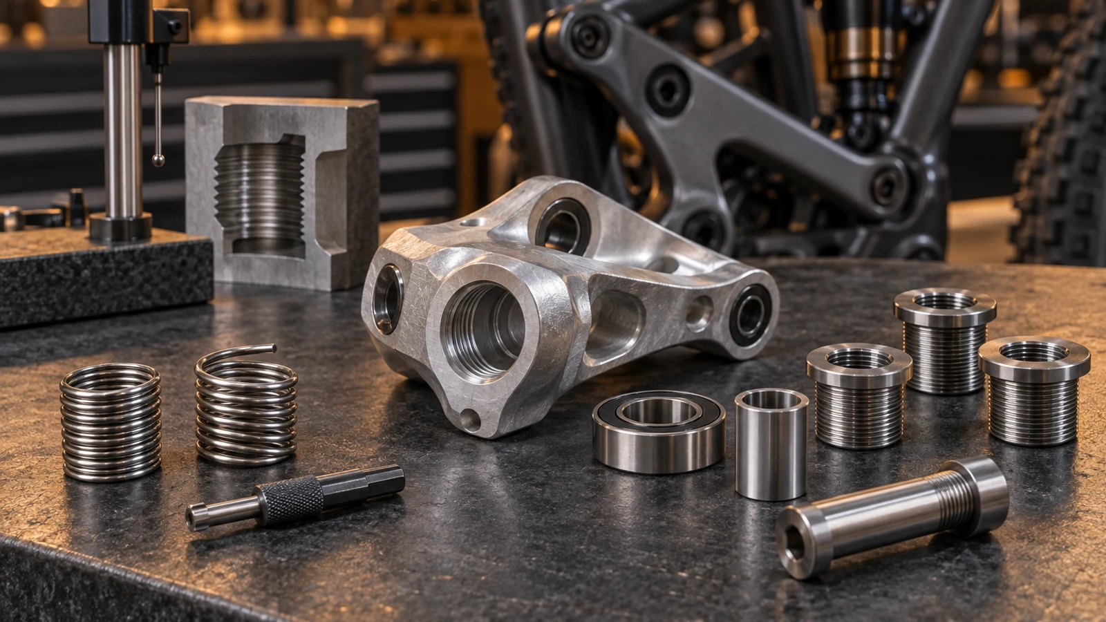
For a bicycle pivot receiver, choose between a coil insert and a flanged solid insert only within a component-specific approved repair. Neither product name establishes adequate remaining wall, correct alignment or a safe tightening value. Compare the exact insert and tooling with the receiver's material, existing damage, bearing and shoulder relationships, and available axial space. Also distinguish retention of the insert in its parent part from locking of the pivot bolt inside it. A blind hole can accommodate an insert body yet lack installation-tool clearance. If those interfaces cannot be established, a commercially available kit is not sufficient evidence to release the repaired assembly.
Hero: concept illustration of example hardware and its application. It is not a factory photograph, tested component or approved production geometry.
Compare mechanisms rather than brand reputations
Böllhoff describes HELICOIL wire inserts with free-running and screw-locking variants, plus variants with different tang arrangements. A coil is therefore not one fixed installation or locking concept. Identify the exact series instead of assuming every coil has a removable tang or adds prevailing resistance to the bolt.
TIME-SERT describes a solid bushing with a positioning flange and an installation-formed retention feature at its lower threads. Those features explain its placement and retention mechanism, not a universal advantage in a bicycle receiver. The comparison needs the actual system specification, not generic claims that one brand is cheaper or stronger.
The stripped-receiver guide addresses whether the damaged component has an authorized repair route. Here the narrower question is how candidate insert architectures affect that route once its scope is established.
Draw the parent feature and seating surfaces together
Place the proposed prepared hole and insert envelope on the receiver drawing. Compare remaining material toward nearby edges, bores and reliefs, not just an outside diameter measured at one convenient face. A thin local ligament or intersecting feature can limit a candidate despite adequate material elsewhere.
Review the solid insert's flange seat against any bearing, spacer or bolt shoulder contact. A positioning feature must not become an unintended stand-off that changes the assembly stack. A coil's installed position also needs definition; absence of a flange does not make its location irrelevant.
These are geometry checks, not minimum-wall rules supplied by this article. Use the insert manufacturer's requirements and the responsible component design review. Pivot fit and datum definition helps communicate the relationships that must remain controlled.
| Decision feature | Coil candidate | Flanged solid candidate | Risk and verification |
|---|---|---|---|
| Parent feature | Selected preparation envelope | Selected preparation and flange recess | Check local walls, edges and adjacent bores |
| Installed position | Specified coil position | Specified flange seat | Verify no changed bearing or shoulder stack |
| Blind-hole access | Variant-specific tools and tang method | Tap relief and driver travel | Compare full tool envelope with available depth |
| Internal bolt behavior | Free-running or screw-locking variant | Insert retention is a separate function | Confirm released bolt locking and preparation |
| Thread and axis | Engagement and location requirements | Engagement and location requirements | Accept specified geometry, not smooth entry alone |
| Strength comparison | Application evidence required | Application evidence required | No universal brand ranking or raised torque |
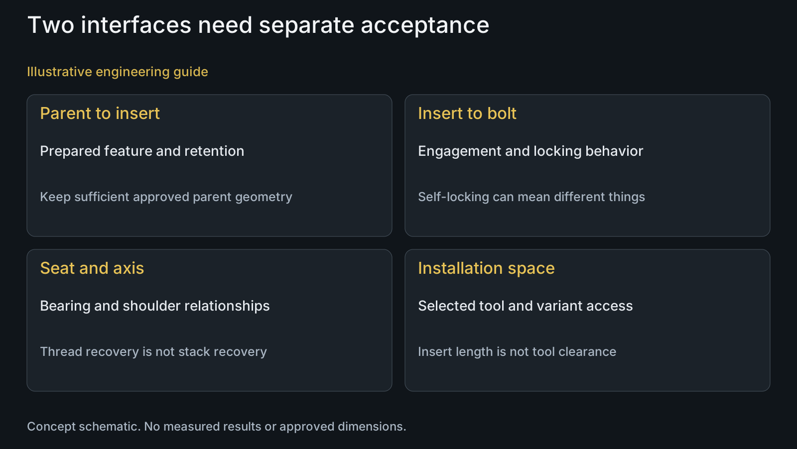
Budget tool travel separately from insert length
A blind receiver requires an axial section showing usable thread, hole bottom, adjacent features and the selected tooling envelope. Insert length alone does not describe the preparation and installation space. Tap entry and relief geometry can require space beyond the full thread needed in service.
TIME-SERT's FAQ specifically identifies additional space for tap relief and for its driver to pass the insert's lower threads during retention formation. It notes that tooling geometry varies. Do not transfer an example depth allowance to every thread size or receiver.
For a selected coil variant, review its own preparation and installation instructions, including any tang operation and debris access. Keep bearings and neighboring cavities in the access review. This comparison does not authorize drilling deeper, breaking through a wall or substituting an installation tool.
Separate insert retention from pivot bolt locking
An insert must stay in the receiver, while the bolt must meet the assembly's separate engagement and retention requirements. These are distinct interfaces. A solid insert's self-locking installation feature should not be read as a released bolt-locking method.
A screw-locking coil is a deliberately different internal-thread variant from a free-running coil. That selection changes the bolt interface and must be considered in the approved assembly method. Do not silently substitute it because a previously assembled pivot loosened.
Retain the specified bolt preparation, locking element and tightening method unless the component authority releases a change. The locking-method comparison explains why adhesive, prevailing resistance and separate retainers cannot be exchanged solely on appearance.
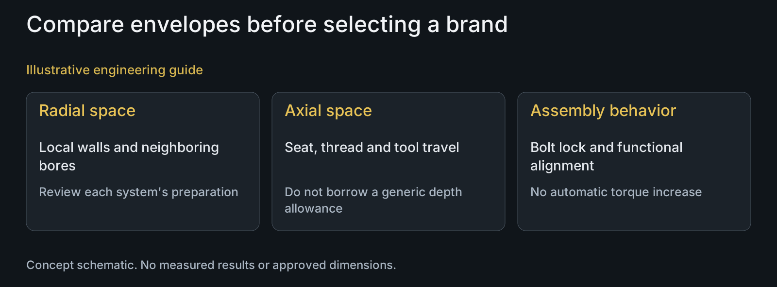
Require more than a thread that accepts the bolt
A matching internal designation establishes only part of compatibility. Review thread engagement and runout with the bolt's shoulder and tip position, together with the thread axis relative to the required bearing or seating datums. A bolt entering smoothly is not proof that those relationships survived repair.
TIME-SERT does not provide a universal torque or pullout specification in its FAQ, citing installation, parent material and insert length among the variables. Accordingly, this article assigns neither a strength ranking nor an increased tightening value to an insert brand.
The approved acceptance plan must address the repaired geometry and assembly function. Dimensional results do not by themselves establish fatigue life. For a new OEM part, manufacturing review can address drawing-based features; it does not create authorization to modify an existing frame.
Review example: a compact blind receiver
Illustrative engineering example: assume an authorized review is comparing a free-running coil with a flanged solid insert in a detached aluminum linkage receiver. The original bolt designation is known, but the receiver is close to a neighboring bearing pocket. No approved dimensions, strength result or completed repair is supplied.
The reviewer overlays each selected system's preparation envelope and tooling travel. One proposal may affect the seat through its flange recess; another may need a tang operation that is inaccessible in the planned setup. Neither concern can be settled by comparing the price of the loose inserts.
The decision remains open until the component review resolves remaining geometry, seating, engagement, tool access and the bolt-locking method. If neither candidate meets those constraints, the correct outcome is not to force a preferred brand into the receiver. This is an illustrative comparison, not evidence of a successful repair.
Questions buyers need to confirm
Is Time-Sert always stronger than a coil insert?
No universal ranking is established here. Parent material, remaining geometry, engagement, alignment and installation affect the assembly. Compare application-specific evidence and the authorized acceptance requirements rather than a brand-level strength claim.
Does a self-locking solid insert lock the pivot bolt?
Not automatically. The cited solid system's installation feature retains the insert in the parent part. Bolt locking is a separate interface and requires its released preparation or retention method. Identify exactly what the product's locking description means.
Are all HELICOIL inserts screw-locking and tang-equipped?
No. The manufacturer describes free-running and screw-locking variants and different tang arrangements. Supply the exact series and size for review; these choices change internal-thread behavior, installation access and debris handling.
Can we select insert length from the blind-hole depth alone?
No. Compare usable engagement, tip and shoulder positions, tap geometry, driver travel and adjacent features. The selected installation tools can need space beyond the insert body. A generic extra-depth allowance is not a substitute for that system-specific section review.
Can an insert flange sit above the original receiver face?
Only if the approved geometry explicitly accommodates it. An unintended stand-off can change bearing, spacer or shoulder contact. Show the flange seat in the assembly section and verify the released stack instead of assuming protrusion is harmless.
What information is needed for an OEM insert-interface review?
Provide receiver material, damage or proposed feature definition, sectional drawing, bearing and seating datums, exact insert system and tooling information, bolt geometry and released locking method. Include repair authority and acceptance scope. These inputs enable comparison without inventing safe wall limits or torque.
Technical references and scope
Böllhoff HELICOIL Thread Inserts for Metals. Named free-running, screw-locking and tang variants; no manufacturer marketing guarantees or universal pivot application adopted.
TIME-SERT Frequently Asked Questions. Solid bushing, flange, installation retention, blind-hole tooling clearance and absence of universal torque/pullout specifications. No numerical allowance or automotive repair procedure transferred to bicycle hardware.
Explore related component, material and sourcing decisions in the customer decision knowledge center. For a drawing review, use the Drawing/BOM RFQ path.
Review the insert and pivot interfaces as one drawing package
Share receiver and pivot drawings or STEP, relevant assembly sections, BOM, exact insert proposal, tool-clearance information and the authorized acceptance requirements. PremFixer can review drawing-based custom hardware and manufacturability. Existing bicycle repair approval and release remain with the responsible component authority; a matching bolt is not a repair certificate.
Discuss the drawing and BOM