
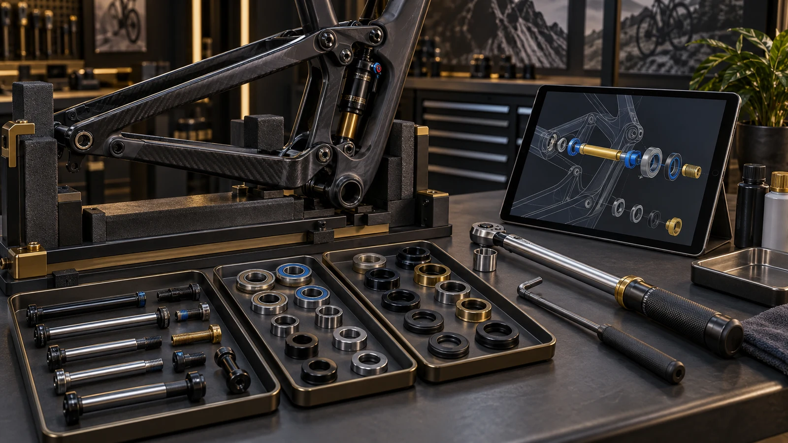
Pivot hardware assembly instructions should specify the approved method for the identified frame joint, not a universal order for all suspension bolts. The OEM is deciding how an operator will reproduce the intended stack, surface condition and tightening state without improvisation. Give each operation an identifiable component, preparation zone, tool arrangement, sequence and acceptance condition. A final torque value alone does not establish that a spacer seated correctly or a separate locking component was handled in the right order. For an existing bicycle, follow its applicable manufacturer instructions. For a new assembly, release the production instruction only against the validated configuration and explicitly define any different service conditions.
Hero: concept illustration of example hardware and its application. It is not a factory photograph, tested component or approved production geometry.
Start with an operation map, not a generic torque chart
Locate every axle, bolt, receiver, spacer and locking element in the assembly drawing. Give left and right positions unambiguous identifiers when their appearance is similar. Show orientation and the stack order where these cannot be inferred from a loose component.
Separate inserting an axle, seating the stack, tightening the load-carrying fastener and engaging a secondary retention element. Which operations exist, and their order, depend on the design. A shared word such as pivot does not make different mechanisms interchangeable.
The torque-specification development guide addresses establishing an approved setting through analysis and assembly evidence. This guide addresses transferring that approved method into executable operations without losing its conditions.
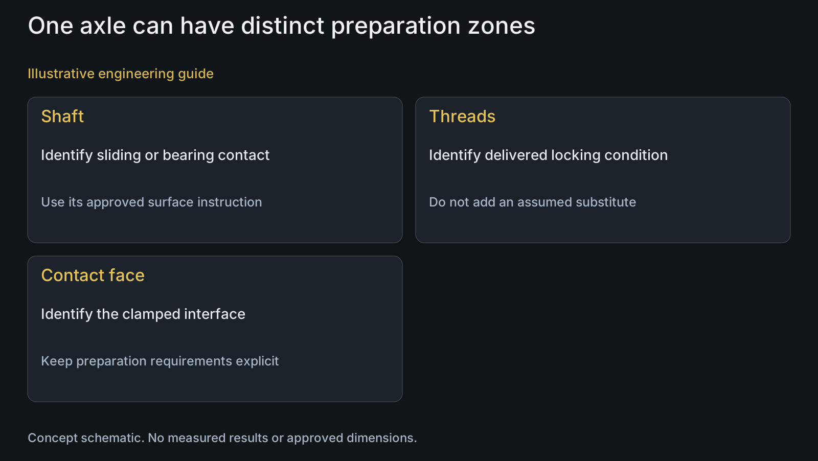
Identify preparation by surface, not by the whole bolt
A shaft, thread, head contact and seal surface may have different requirements. Use an annotated view to distinguish the permitted application zones and identify the specified product or delivered coating. Do not replace that information with an instruction to grease the bolt.
Santa Cruz's 5010 5 MY25 support table provides a useful public example of this distinction: selected pivot axles have separate threadlocker and shaft-grease notes linked to part identities. Those instructions belong to that model's hardware, not an approval for PremFixer parts or another frame.
State any required cleaning, application, handling and waiting conditions from the approved procedure and controlling product information. Keep an unknown pre-applied coating identifiable at receipt. A visually similar liquid or coating is not a silent substitute; review its effect through the surface-treatment manufacturing scope.
| Instruction approach | When it helps | Risk if used alone | Verification needed |
|---|---|---|---|
| Generic diameter-based setting | Background reference only | Receiver, surface and stack conditions omitted | Configuration-specific development basis |
| Joint-specific final setting | Approved tightening operation | Preparation or counter-hold still ambiguous | Correct item, surface state and tool arrangement |
| Annotated surface map | Different shaft and thread requirements | Application amount or compatibility unresolved | Controlling procedure and product identity |
| Named sequence and intermediate states | Multiple dependent assembly operations | Copied order may not fit this mechanism | Representative assembly and access review |
| Separate service instruction | Reuse or replacement differs from production | Old compounds or worn parts assumed equivalent | Allowed component and preparation conditions |
Describe the required intermediate states and tool arrangement
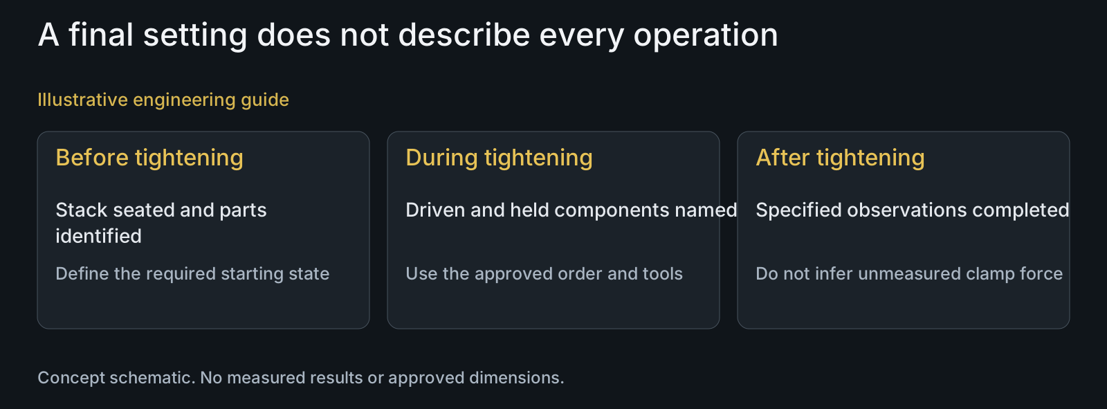
Explain what must be aligned, supported, seated or held before each controlled tightening operation. Where two tools are needed, show the driven component and the counter-held component. Access clearance matters: an instruction that names a socket but leaves no usable approach cannot be executed as written.
Write the approved sequence using the actual joint identities. A central-first order, cross pattern or staged tightening method may be valid for a particular assembly, but it is not established by a general frame description. Do not introduce percentage stages simply because they look systematic.
Distinguish an intermediate seating action from the final controlled operation. Specify units and the applicable setting, range or other approved control without inventing one here. If the instruction leaves the operator to choose which component rotates, that ambiguity needs design review rather than a stronger tool.
Make abnormal assembly response an explicit stop condition
Define observations that require pausing and identifying the cause, such as unexpected resistance before the intended contact, a missing spacer, visible stack mismatch or failure of an agreed movement check. Name the responsible review path rather than encourage an improvised lower setting.
A tool reaching its setpoint and a joint meeting its functional requirement are separate observations. Likewise, a record that a setting was applied is not automatically a direct clamp-force measurement. Specify what the operation actually verifies and what remains outside that check.
Use the pivot tolerance-stack guide when seating or movement differs from the intended relationship. Changing torque to disguise an unresolved geometric problem does not establish the correct assembly condition.
Keep production and service instructions applicable to their own state
Production may start with new components and a controlled delivered surface. Service may involve previously tightened parts, remaining compounds and replacement components. Specify allowed reuse and preparation rather than assume the original production state still exists.
Santa Cruz's bearing and pivot maintenance guidance directs reassembly to model-specific torque and grease/threadlocker specifications. The transferable lesson is to retain the correct configuration reference, not to adopt that manufacturer's maintenance interval or hardware procedure for every bicycle.
When a finish, mate, locking feature or tool arrangement changes, identify which operation and supporting evidence are affected. PremFixer's manufacturing review can connect the supplied hardware state to the proposed instruction; application validation and instruction approval remain explicitly assigned project responsibilities.
Review example: the same setting with a different delivered coating
Illustrative engineering example: assume an OEM has an approved assembly method for a pivot axle and separate locking component. A proposed supply revision changes the thread coating while leaving the geometry and printed torque entry unchanged. No actual torque, friction value or test outcome is assumed.
The reviewer first locates the changed surface and compares its delivered condition with the preparation operation. They then identify whether the earlier tightening evidence, handling instructions and service reuse assumptions still represent the revised configuration. Geometry equivalence does not answer those questions.
The instruction must not continue telling an operator to add a product over the new coating unless that combination is approved. The useful outcome of this review is an identified compatibility and validation question, not an automatic setting correction or a claim that the new assembly is acceptable.
Questions buyers need to confirm
Is there a universal tightening order for suspension pivots?
No. Use the procedure for the actual mechanism, frame configuration and hardware revision. Different load-carrying and locking elements can require different operations. A general central-first or cross pattern cannot establish approval.
Should we add staged tightening percentages to the instruction?
Only when the approved method requires them. Define the joints, intermediate states and final operation that the stages control. Copying percentages from another platform does not validate the sequence or its effect on this stack.
Can the instruction simply say to grease the pivot bolt?
Not when different surfaces have different requirements. Identify the shaft, threads and contact faces, the specified product or pre-applied state, and relevant preparation conditions. Otherwise an operator may alter a surface that the validated method treats differently.
What should happen if resistance rises before the stack seats?
Pause and investigate against the identified assembly state. Check component identity, orientation, engagement and intended contact before continuing. Reaching a tool setting early does not prove seating, and an improvised torque change does not resolve the cause.
Can the production procedure be reused for service?
Only after its applicability is established. Compare new versus reused components, remaining compounds, allowed replacement parts and preparation. A service instruction must define those conditions rather than silently inherit a new-part assembly assumption.
What should we provide for an assembly-instruction review?
Provide the assembly drawing, joint identities, hardware revisions, surface-zone requirements, existing validated method and proposed tools. Include service reuse conditions and unresolved seating or access observations so the review can identify precisely which operation needs clarification.
Technical references and scope
Santa Cruz 5010 5 MY25 support table. Public model-specific hardware entries distinguish thread and shaft preparation. No numeric setting, part compatibility or approval is transferred to another design.
Santa Cruz bearing and pivot axle maintenance guidance. Reassembly refers to model-specific torque and preparation requirements. Manufacturer-specific maintenance intervals and hardware service actions are not generalized.
Explore related component, material and sourcing decisions in the customer decision knowledge center. For a drawing review, use the Drawing/BOM RFQ path.
Make your pivot assembly method unambiguous
Send the assembly drawing or STEP model, hardware BOM, approved tightening basis, surface requirements and proposed tool arrangement through the Drawing/BOM RFQ path. PremFixer can review supplied-part definitions, preparation boundaries and assembly access with your team, while keeping validation and instruction approval responsibilities explicit.
Discuss the drawing and BOM