
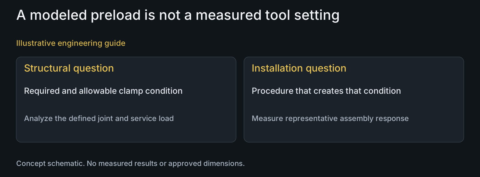
A new custom pivot assembly needs a torque specification derived from the complete joint, not from bolt diameter or a chosen safety factor alone. First establish the required clamping function and the limits of the bolt, receiving thread, contact faces and bearing arrangement. Use analysis to examine the proposed preload and service loads. Then test the representative assembly to connect its tightening procedure with clamp load and functional response. Material condition, surface finish, lubricant, locking product, tool and sequence belong to that configuration. A model that starts with an assumed preload cannot by itself prove which installation torque creates it in the delivered hardware.
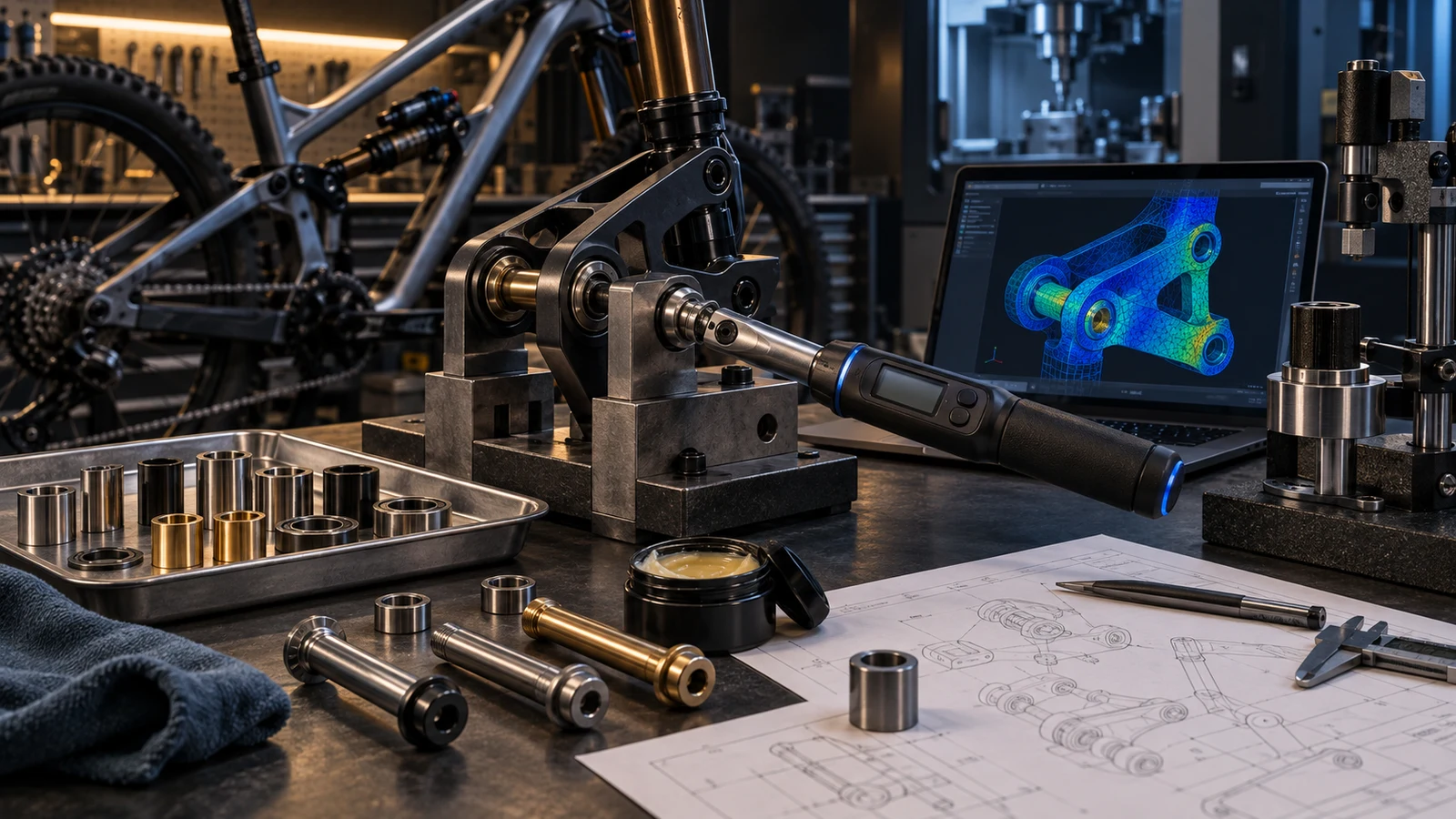
Hero: concept illustration of example hardware and its application. It is not a factory photograph, tested component or approved production geometry.
Define what the pivot clamp load must achieve
Map the axial contact path before choosing a setting. Identify which inner rings, spacers, shoulders and receiver faces are intended to carry clamping force, and which components must remain free to move. A bottomed shoulder or an incorrect spacer can change that path even when the torque tool reaches its setpoint.
Describe the service loads and acceptable movement, separation, contact pressure and bearing behavior. Assess the bolt and receiving thread alongside the rest of the joint. A strong bolt does not justify an installation setting that damages a weaker receiver or creates an unintended bearing condition.
Set project-specific criteria for each relevant failure or functional concern. State how margins are defined and which material and loading assumptions support them. No single safety-factor target is adopted here as a bicycle requirement, and a factor without a defined limit state does not produce a torque instruction.
Use the model to examine preload, not invent its delivery
Include the assembly contacts, restraints, material conditions and service loads needed for the question. An idealized bolt may help assess overall load transfer, but it does not automatically resolve local thread strength, detailed bearing behavior or friction during installation. Identify what the model represents and what requires a separate check.
Ansys documents applying bolt pretension, then holding the shortened grip condition while subsequent structural loads are applied. This distinguishes assembly preload from later loading. It is a modeling method, not a substitute for evidence that the chosen production tightening process delivers the assumed initial state.
Review a credible preload range rather than one convenient value. Examine the consequences of lower clamp load and higher assembly loading for the relevant limits. Compare the model with accessible physical responses, and retain uncertainty where contact, friction or material inputs are not established.
| Evidence | Useful decision | Important limitation | Configuration to define |
|---|---|---|---|
| Preloaded structural model | Response to assumed clamp and service loads | Does not measure how installation creates preload | Contacts, restraints, material and preload range |
| Torque-to-clamp test | Relationship between tightening and measured clamp | Fixture may differ from the actual pivot | Surfaces, compounds, mates and instrument arrangement |
| Torque-angle record | Tightening progression for the selected procedure | Angle is not automatically direct clamp measurement | Tool, sequence, seating and response interpretation |
| Destructive torque test | Failure response of the tested configuration | Failure torque is not an installation setting | Receiver, engagement and observed failure location |
| Assembly-function assessment | Movement and bearing behavior after tightening | Smooth movement alone does not prove all load limits | Actual stack, mating geometry and acceptance criteria |
| Service validation | Behavior under the intended usage conditions | Not transferable to unspecified configurations | Load history, hardware state and application scope |
Establish the actual tightening and friction configuration
Specify the thread pair, head or washer contact, finished surfaces and lubricant application. Also define locking products and reuse condition. Bossard's torque calculation interface treats thread friction and head contact friction as separate inputs; a material name alone does not describe either interface.
The purpose of representative tightening tests is to connect the applied procedure to the resulting assembly state. Record torque and, where useful, angle together with the selected clamp measurement and functional observations. Name the tightening speed, sequence and equipment rather than report only a peak number.
Keep running resistance from a locking feature distinguishable from the resistance associated with generating clamp load. The pivot retention guide covers method selection. Its retention discussion does not establish a universal adjustment to this joint's installation setting.
Choose evidence that answers the assembly question
A torque-to-clamp test, a destructive torque test and a service-function test answer different questions. The first relates a tightening input to a measured response; the second examines a defined failure configuration; the third addresses the joint in its intended use. None is automatically interchangeable with the others.
ISO 16047 describes torque/clamp-force testing for threaded fasteners and related parts within a defined scope. Its public abstract excludes fasteners with additional self-locking features. Check applicability and the agreed procedure before labeling a coated or locking pivot test as conformity to that standard.
Use specimens and mating parts representative of the proposed released configuration, while documenting instrument or fixture changes that alter the load path. Assess assembly movement and intended pivot function as well as the chosen mechanical measurements. The destructive torque guide explains why failure torque alone is not an installation recommendation.
Release the instruction with its applicable configuration
An approved instruction needs units, joint position, hardware and receiver identities, surface and compound condition, tightening sequence and tool requirements. State the allowed reuse or replacement condition and who owns approval. A production setting should not be copied into a service instruction if the service configuration differs.
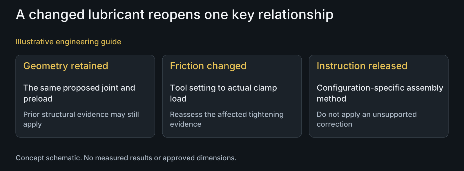
A finish, lubricant, locking product or mating-part change can require renewed assessment. Identify which evidence remains applicable and which relationship has changed. Do not impose a blanket percentage correction from another compound or use a removal reading to reconstruct the original clamp load.
PremFixer's manufacturing review can connect the specified component and treatment state to the proposed supply scope. Analysis ownership, testing arrangements and application approval remain explicit project responsibilities; this article does not claim an owned FEA or torque-validation laboratory.
Review example: the model is unchanged but the lubricant changes
Illustrative engineering example: assume an OEM has modeled a pivot at a proposed preload and is evaluating a tightening procedure for its sample assembly. The bolt geometry remains unchanged, but the proposed supply introduces a different lubricant. No numerical preload, torque, friction coefficient or test outcome is assumed.
The team checks whether the lubricant changes the tightening-to-clamp relationship and whether it is compatible with the locking and surface requirements. The structural model can still examine the same proposed preload, but that does not confirm that the earlier tool setting will create it under the changed conditions.
Representative assembly evidence must support the revised procedure before its release. The distinction is useful: a valid structural assessment need not be discarded automatically, yet it cannot be used to bypass validation of the changed installation method.
Questions buyers need to confirm
Can FEA directly approve the installation torque?
Not from an imposed preload alone. The model assesses the configured joint at assumed loading. The tightening procedure still needs evidence connecting its tool input to actual clamp and function, including the relevant surfaces, compounds and mating components.
Can we copy a value from a bolt of the same diameter?
No configuration-specific approval follows from diameter alone. Compare the receiver, engagement, contact path, material conditions, finish, lubricant and locking arrangement. For an existing bicycle use its approved instruction, not a development example or generic chart.
Is a torque test the same as clamp-load measurement?
No. Identify the measured quantities and fixture. Applied torque, angle, running resistance, clamp force and failure torque have different meanings. Specify which relationship the report establishes and how it applies to the actual assembly.
What if the pivot becomes stiff after tightening?
Investigate the intended contact path, spacers, shoulders and bearing arrangement against the approved configuration. Stiff movement is not a reason to publish an improvised lower setting. Determine whether geometry, hardware or the developed instruction is inconsistent with the intended function.
Does a specified safety factor establish the torque?
No. Define the limit state, loads and material basis for that factor. The joint can have several limiting features, and the installation-to-clamp relationship requires its own evidence. No universal factor or torque follows from this guide.
What changes require reassessing the instruction?
Review changes to receivers, geometry, finishes, lubricants, locking products, tools, sequence and reuse state. Identify the affected evidence rather than apply a universal correction. Supply the revised configuration and the existing validation basis for that comparison.
Technical references and scope
Ansys Discovery bolt preload documentation. Pretension followed by held grip length and structural loading; modeling methodology, not production validation or bicycle acceptance.
Bossard torque and preload calculator inputs. Distinct thread and head friction inputs and specified geometry. Default numeric calculator results are not transferred to a pivot.
ISO 16047 public abstract. Torque/clamp-force testing scope and exclusions. Full procedure and amendment requirements require the controlling document; no conformity or installation limit inferred.
Explore related component, material and sourcing decisions in the customer decision knowledge center. For a drawing review, use the Drawing/BOM RFQ path.
Connect the joint model to the intended assembly procedure
Send the pivot and receiver drawings, stack arrangement, material and finish conditions, lubricant or locking product, tool and sequence, and available analysis or test scope. Identify the required clamp function and limiting features so the review can separate component manufacture, tightening validation and application approval.
Discuss the drawing and BOM