

A pivot bolt fillet should not be enlarged independently of its mating washer, spacer or bearing interface. The transition shape and the available corner clearance must work together so the intended faces can seat. For an OEM comparing a radius revision with a machining simplification, identify the loaded transition, the contacting member and the required contact region first. Then review both parts across their specified dimensional conditions. A chamfer for insertion, a burr-removal edge break and a fillet at a loaded shoulder perform different tasks. Neither a larger radius nor a generic chamfer note establishes a fixed stress reduction or a validated pivot assembly.
Hero: concept illustration of example hardware and its application. It is not a factory photograph, tested component or approved production geometry.
Separate three geometries that perform different jobs
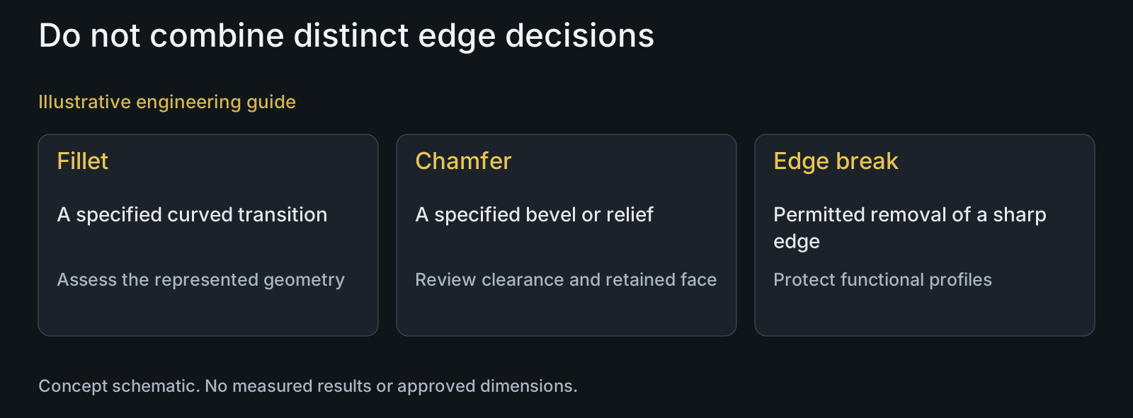
A fillet defines a curved transition between adjacent surfaces. A chamfer defines a bevel. An edge-break instruction addresses an otherwise sharp edge, but may not specify the particular shape needed at a functional interface. Do not use these terms interchangeably on a pivot drawing.
As engineering analysis, changing a loaded transition changes the local geometry that a stress assessment must represent. That observation does not supply a universal best radius or a fatigue improvement. Preserve the surrounding section, bore and loading assumptions when evaluating a proposed change.
An entry chamfer can serve insertion clearance without replacing the intended shoulder transition. Identify exactly which edge each note controls. A workshop-wide deburr instruction should not silently overwrite a deliberately defined radius, bearing seat or contact boundary.
A radius proposal must leave room for the mating corner
NSK's bearing handling instructions, section 2.7, discuss shoulder contact, perpendicular faces and corner fillet dimensions together. Its bearing-specific dimensions are not generic prescriptions for every bicycle axle or washer.
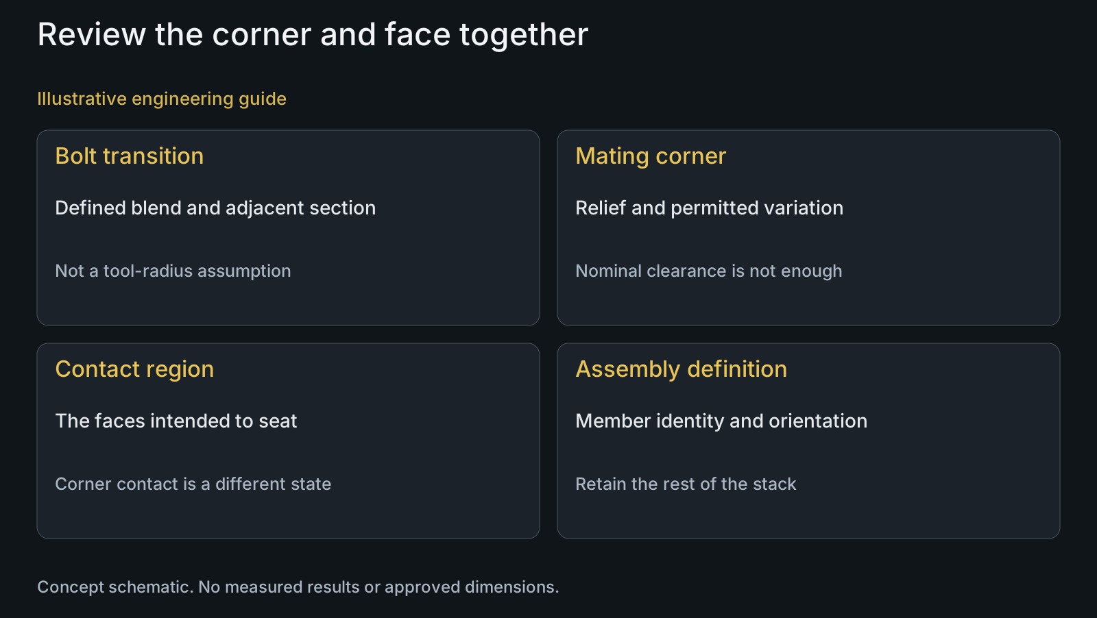
Identify the actual contacting ring or spacer face, rather than assuming the whole bearing is clamped in the same way. Compare the transition envelope with the mating edge relief and the intended support face. Include specified variations of both members; nominal CAD clearance alone does not resolve the interface.
Keep the required shoulder contact region visible in the review. Removing more material from a mating corner may create clearance, but it also changes the available face. A proposed relief needs its own definition rather than an instruction to chamfer until the assembly fits.
| Feature | Primary decision | Risk if treated as interchangeable | Useful verification |
|---|---|---|---|
| Loaded shoulder fillet | Defined transition with compatible mating clearance | Larger radius prevents intended face contact | Profile and adjacent geometry; represented load analysis |
| Underhead washer relief | Room for the actual bolt transition | Corner contact mistaken for flat seating | Both-part geometry and washer orientation |
| Bearing shoulder interface | Support the intended ring face with corner clearance | Nominal radius selected without the bearing definition | Manufacturer interface requirements and contact region |
| Entry chamfer | Insertion path and defined bevel | Bevel substituted for a loaded blend | Chamfer limits and affected locating surface |
| General edge break | Removal of an unspecified sharp edge | Functional profile changed during deburring | Explicit protected features and permitted edge condition |
Underhead clearance is different from tightening resistance
As a scoped historical reference, section 4.7.3 of NASA-STD-5020A with Change 1 addresses head-to-shank fillet interference and relieved holes or washers in spaceflight fastening systems. It is not a bicycle compliance requirement; the relevant lesson is to check whether the intended faces can contact.
A washer that touches the curved transition before its flat face seats presents a different contact condition from the drawing's intended flat support. Do not accept that condition merely because the screw can be tightened. Resistance during tightening is not a measurement of complete face seating.
When a relieved washer is specified, show its orientation and relevant dimensions in the assembly definition. Changing its thickness or substituting a visually similar washer can also alter the stack and usable engagement. Clearance corrections must retain those other interface requirements.
Define the finished transition before asking how it will be made
State the required profile and its location relative to the adjacent surfaces. A radius value without a clear feature reference can leave different interpretations of where the blend begins or ends. Include any required contact boundary and the supplied surface condition.
The CNC turning review can assess tool access and the sequence needed to produce that definition. A tool nose radius is a process input, not automatically the finished drawing radius. Production feasibility does not authorize a change to the customer's load-bearing geometry.
Select an inspection method that addresses the defined shape and location. A dimensional check on the straight shank does not establish the blend profile. A trial assembly can reveal a contact concern, but it does not replace specified profile acceptance or application validation.
A larger fillet can solve one question and create another
Illustrative engineering example: assume an OEM proposes enlarging an underhead fillet while retaining an existing washer. The washer drawing specifies an inner corner relief, but the proposal has not compared that relief with the revised transition across their dimensional limits.
The review first identifies the intended flat contact region. It then compares the revised bolt profile with the washer's allowed inner edge. If corner contact could prevent that face from seating, the revision is incomplete even if a local stress model favors its transition.
The designer can evaluate a coordinated interface revision or retain a compatible transition. Either choice needs the approved drawings and relevant joint assessment. This example reports no actual interference measurement, successful redesign, stress percentage or component test; it illustrates why a single-part improvement is not yet an assembly decision.
Send the mating definition with the transition request
Provide the bolt drawing and STEP together with the contacting washer, bearing or spacer definition and assembled stack. Mark the proposed change and identify the surfaces that must seat. A sample can help communicate the interface, but it does not establish an unrecorded permissible radius.
The surface-processing review addresses the supplied finish, while the roughness and fatigue guide explains why finish evidence cannot establish a geometry-specific life gain. The pivot FEA scope guide addresses which configuration an analysis actually represents.
PremFixer manufactures to the agreed customer interface definition. Request a manufacturing review of the transition, tool access and verification scope, while keeping design approval and joint validation with the responsible project team. Do not describe a concept image as an approved seating arrangement.
Questions buyers need to confirm
Is a larger pivot fillet always better?
No. Review the loaded geometry and mating corner together. The revised transition must permit the intended seating and preserve adjacent functional features; a local geometry preference is not complete joint approval.
Can a chamfer replace a specified fillet?
Not without an approved change. A bevel and curved blend define different shapes. Identify the location, mating clearance and load context before treating either as an acceptable alternative.
Why does a washer need an inner edge definition?
Its corner may need to clear the head-to-shank transition. Provide the actual relief and orientation, and retain the required flat contact region and stack dimensions rather than accepting tightening resistance as seating evidence.
Can one bearing catalogue radius be used for every pivot shoulder?
No. Identify the actual bearing and contacting member. Its corner clearance and shoulder-support requirements must be reviewed with the axle geometry; a generic value does not establish compatibility.
Does the turning insert radius prove the finished fillet?
No. The resulting profile also depends on the machining definition and setup. Specify the finished feature and an appropriate verification method instead of substituting a tooling label for acceptance.
What should accompany a fillet or chamfer revision RFQ?
Send both mating drawings or interfaces, STEP, assembled stack, material and finish, quantities and marked contact regions. Identify the proposed change and available analysis so manufacturing feasibility is separated from design approval.
Technical references and scope
NSK: Handling instructions for bearings, section 2.7. Pages20–21 relevant complete mounting-precaution text and table headings read. Qualitative shoulder contact and corner relationship only; no numerical recommendations transferred.
NASA-STD-5020A with Change 1, section 4.7.3. Complete relevant underhead-clearance requirement and rationale read. Explicit historical spaceflight example, not current bicycle compliance or other NASA installation requirements.
Explore related component, material and sourcing decisions in the customer decision knowledge center. For a drawing review, use the Drawing/BOM RFQ path.
Review your transition and mating clearance together
Send the bolt and mating-member drawings, STEP, stack definition, supplied finish and quantities. Mark the intended seating surfaces and proposed edge change. PremFixer will review the manufacturable transition and verification scope without assigning an unsupported stress or fatigue gain.
Discuss the drawing and BOM