
Balance weight and stiffness in road suspension hardware by defining the mechanism's permitted movement and the deformation it must resist. A rider-compliance interface may intentionally allow motion in one direction while requiring support in another; simply maximizing stiffness can defeat that function. Compare a lightweight proposal with the same assembly supports, contacts and included parts as the baseline. A road label does not make its pivot a low-load MTB joint or approve 7075 aluminum. The OEM must establish the actual mass boundary, directional response and application requirements before a change to material, section or contact geometry becomes an acceptable manufacturing specification.
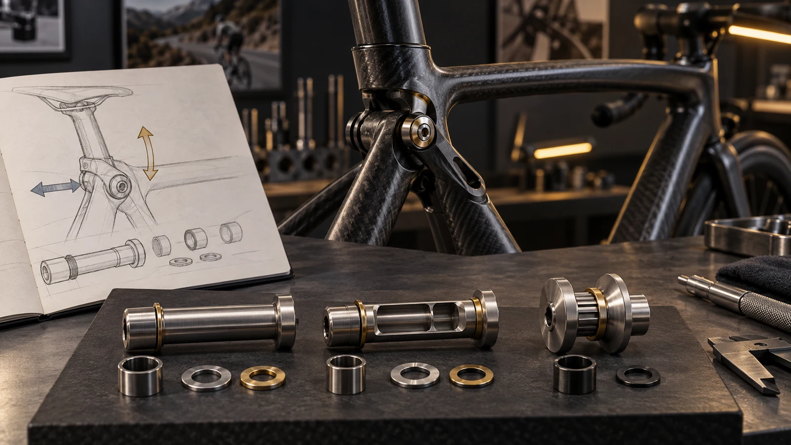
Hero: concept illustration of example hardware and its application. It is not a factory photograph, tested component or approved production geometry.
Name the movement that the hardware serves
Identify the actual mechanism and part function: locating a sleeve, supporting a rotating member, retaining a compliance device or clamping a stationary stack. Show the moving members and intended stops. Do not treat every visible fastener near a comfort feature as a rear-wheel suspension axle.
Trek's Domane Gen 5 white paper describes a seatpost design intended to provide vertical compliance while retaining lateral stiffness. It also explains that this generation omits the earlier IsoSpeed mechanism. These manufacturer-specific examples show why direction and architecture matter; they do not establish a specification for a custom pivot or imply PremFixer supplies those models.
Use the road mechanism and material guide to establish the interface identity. This review then asks a different question: what mass and deformation comparison would let the OEM judge a proposed redesign?
Give the weight target a complete comparison boundary
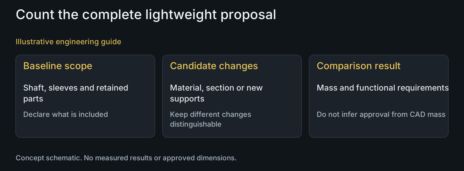
State whether the target applies to the shaft, a hardware set or the complete mechanism. Identify washers, sleeves, retainers and spacers included in both candidates. If a thinner shaft requires another supporting component, its isolated saving does not describe the assembled mass change.
Use a consistent basis for comparison: the same design scope and final condition. CAD mass can support an early estimate when geometry and material inputs are declared; it does not represent an independently measured finished part. Keep estimated and measured values distinguishable without assigning unsupported improvement percentages.
Name protected features before looking for material to remove. A locating shoulder, drive feature, receiver engagement and contact footprint may serve different constraints. Removing a feature because it appears heavy can move the problem into assembly, service or the mating frame rather than solve it.
| Candidate or claim | Compare under the same conditions | Risk | Useful evidence |
|---|---|---|---|
| Lower shaft mass | Complete included hardware set | Added sleeve erases the assumed saving | Declared CAD scope or measured finished set |
| Higher stiffness | Direction, supports and displacement location | Blocking intended compliance | Defined assembled response comparison |
| Unchanged outer geometry | Internal section and material condition | Assuming identical structural behavior | Explicit revised-section assessment |
| Smaller head or flange | Contact footprint and tool engagement | Moving the limit into the mating member | Contact and installation review |
| Aluminum alternative | Actual function and application requirements | Approving a material from road category | Material-specific design and validation basis |
| Good static response | Represented load and assembly conditions | Inferring repeated-load performance | Separate evaluation with stated purpose |
Specify stiffness by direction and assembly boundary
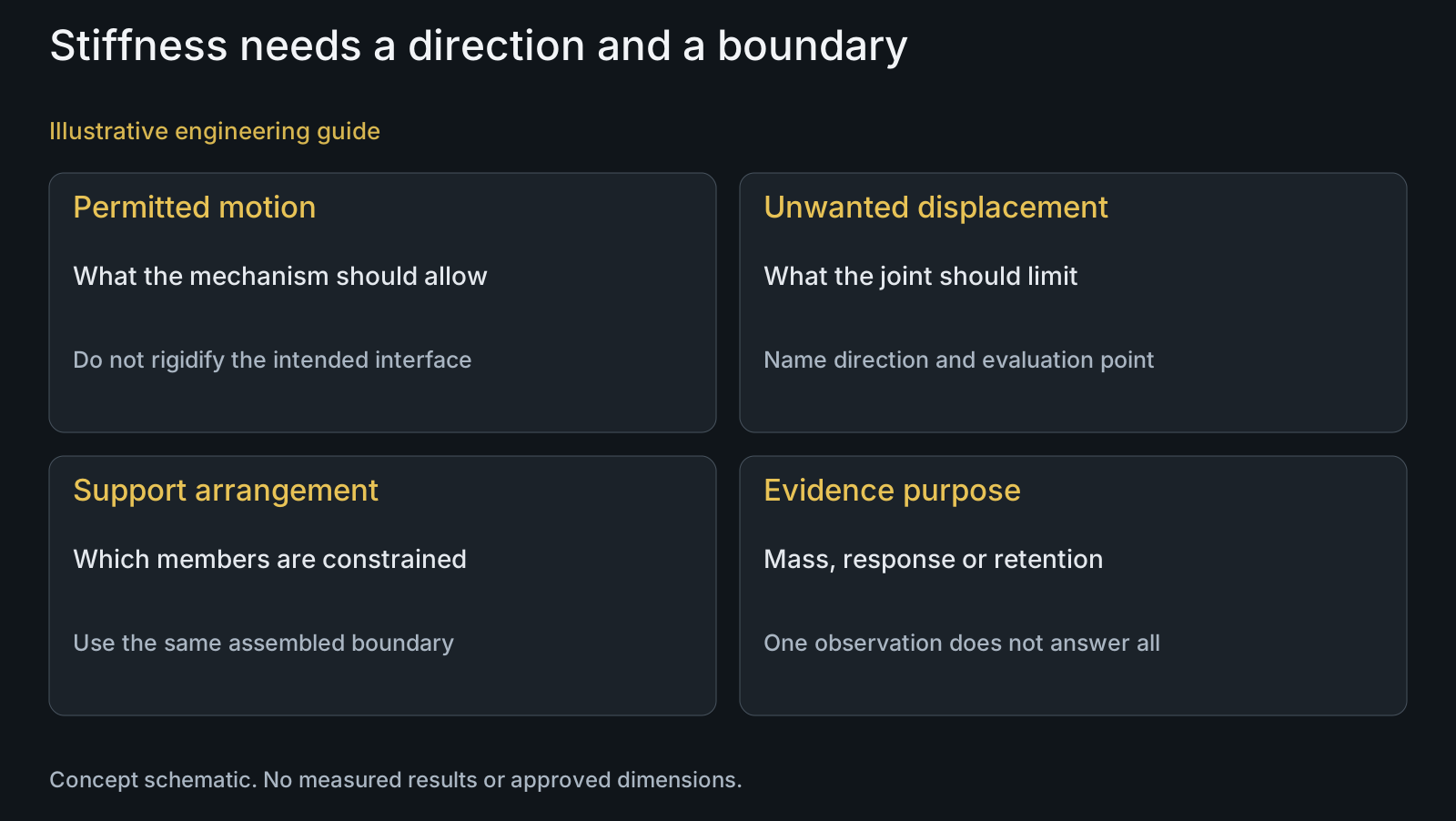
Ask where load is applied, which members are supported and where displacement is evaluated. State the direction of interest and whether the response being assessed is the hardware, its joint or the complete bicycle mechanism. A part-level comparison cannot silently stand in for a system-level result.
Separate unwanted deformation from intended compliance. For example, an allowed relative movement at one interface is not the same as undesired lateral play. The customer needs to define those relationships so a supplier does not propose a rigid contact that removes the intended motion.
Trek's white paper distinguishes a static frame/seatpost measurement from evaluation including other system components and dynamic conditions. Apply that as a scope question, not a claim to possess Trek's test apparatus or results. State which assembly and conditions the project's evaluation actually represents.
Compare alternatives without hiding what changed
A material substitution with unchanged geometry and a hollow-section redesign are different proposals. Identify the actual changed attributes instead of grouping them as a lighter bolt. Each can affect the component response, contact behavior and route needed to make and inspect the finished geometry.
For a hollow option, show the bore termination, remaining wall and transitions. For a smaller head or flange, show the final contact footprint and tool engagement. Inspectability matters too: a proposed feature needs a usable way to establish its required geometry, not just an attractive rendered cutaway.
Discuss access and final feature requirements with CNC turning, and connect alloy questions to the material-selection review. These discussions address manufacturability and requested evidence; neither automatically approves a new structural configuration.
Keep stiffness, retention and fatigue questions distinct
A stiffness comparison describes a response under defined conditions. Retention asks whether the assembly stays in its intended state. Repeated-loading assessment addresses another question. One successful fit check or a favorable CAD mass result does not answer all three.
Include the relevant installation and surface condition in the comparison. Changes to the head contact, thread engagement or locating stack may alter how the joint is assembled. Do not compensate for an unclear support relationship by inventing a higher torque or transfer another mechanism's instructions.
Use the application-specific torque guide where assembly conditions are being changed. The OEM should identify the evaluation purpose and acceptance basis for each candidate, with any numerical target supplied by the responsible design team rather than inferred from road use.
Review example: lighter shaft, additional support sleeve
Illustrative engineering example: assume an OEM proposes a hollow shaft for a road seat-area compliance mechanism. The concept preserves external locating dimensions but adds a support sleeve. The mechanism must retain its intended movement while controlling unwanted lateral displacement. No numerical mass, load or test outcome is assumed.
The reviewer includes the new sleeve in the mass comparison and identifies the same support and displacement locations for both candidates. It also checks whether the sleeve changes the intended moving interface. A smaller shaft mass alone cannot establish a lighter complete mechanism or an equivalent directional response.
The resulting decision identifies the candidate geometry, complete mass scope and separate evidence required for motion, unwanted deformation and retention. The example does not approve aluminum, a hollow shaft or a named bicycle application. It turns an unqualified 'lighter and stiff enough' request into assessable requirements.
Questions buyers need to confirm
Should a road compliance pivot be as stiff as possible?
Not without a directional requirement. Identify intended motion and unwanted displacement, then state supports and the evaluation point. Greater stiffness at an intentionally compliant interface may change the mechanism rather than improve it.
Can road use alone justify an aluminum pivot?
No. Provide the joint function, geometry, material condition and application requirements. Road use does not establish loads at the part or eliminate retention, contact and repeated-loading questions. Evaluate the actual proposed configuration.
Is a hollow shaft lighter when its CAD mass is lower?
Its declared shaft estimate may be lower, but compare the complete included set. Count new sleeves, washers or retainers and distinguish estimated from measured finished mass. The shaft result alone says nothing about equivalent assembled response.
What makes a stiffness comparison reproducible?
State the assembled configuration, load application, supporting members, direction and displacement location. Use the same relevant boundary for both candidates. A different fixture or evaluated component can make the apparent comparison describe a different problem.
Does matching the outside dimensions preserve the original behavior?
Not necessarily. Internal section, material condition and contact relationships can change. Identify the changed attributes and the required response or application evidence; dimensional interchangeability alone does not establish structural equivalence.
What should the OEM send with a lightweight proposal?
Send the mechanism assembly, baseline and candidate drawings or STEP, included BOM, intended movement and constrained directions. Add material and finish definitions, installation conditions, quantities and the requested evaluation scope so manufacturing review addresses the actual proposal.
Technical references and scope
Trek Domane Gen 5 white paper. Manufacturer-specific directional compliance and stiffness context, architectural change and static versus dynamic evaluation boundary. No reported performance numbers, model fitment or supplier relationship adopted.
Explore related component, material and sourcing decisions in the customer decision knowledge center. For a drawing review, use the Drawing/BOM RFQ path.
Define a meaningful road hardware lightweight comparison
Send the baseline and proposed STEP or drawings, mechanism assembly and included BOM. Identify permitted movement, unwanted deformation, mass comparison boundary, materials, final surfaces and the evidence needed for the decision. PremFixer can review candidate manufacturability and feature requirements while the OEM retains application approval.
Discuss the drawing and BOM