
Rolling TC4 titanium pivot threads can be considered for a controlled manufacturing route, but it does not guarantee a fifty-percent fatigue improvement or make every cut thread unacceptable. The comparison must identify the finished thread geometry, material condition, production sequence and loading represented by the evidence. A process name cannot establish those conditions. For OEM engineers and purchasing teams, first decide whether the claim concerns fatigue strength at a defined endpoint or cycle life under a defined load. Then review the actual bolt and receiver configuration. A thread that passes fit inspection has answered a dimensional question, not automatically the fatigue question for the complete pivot.
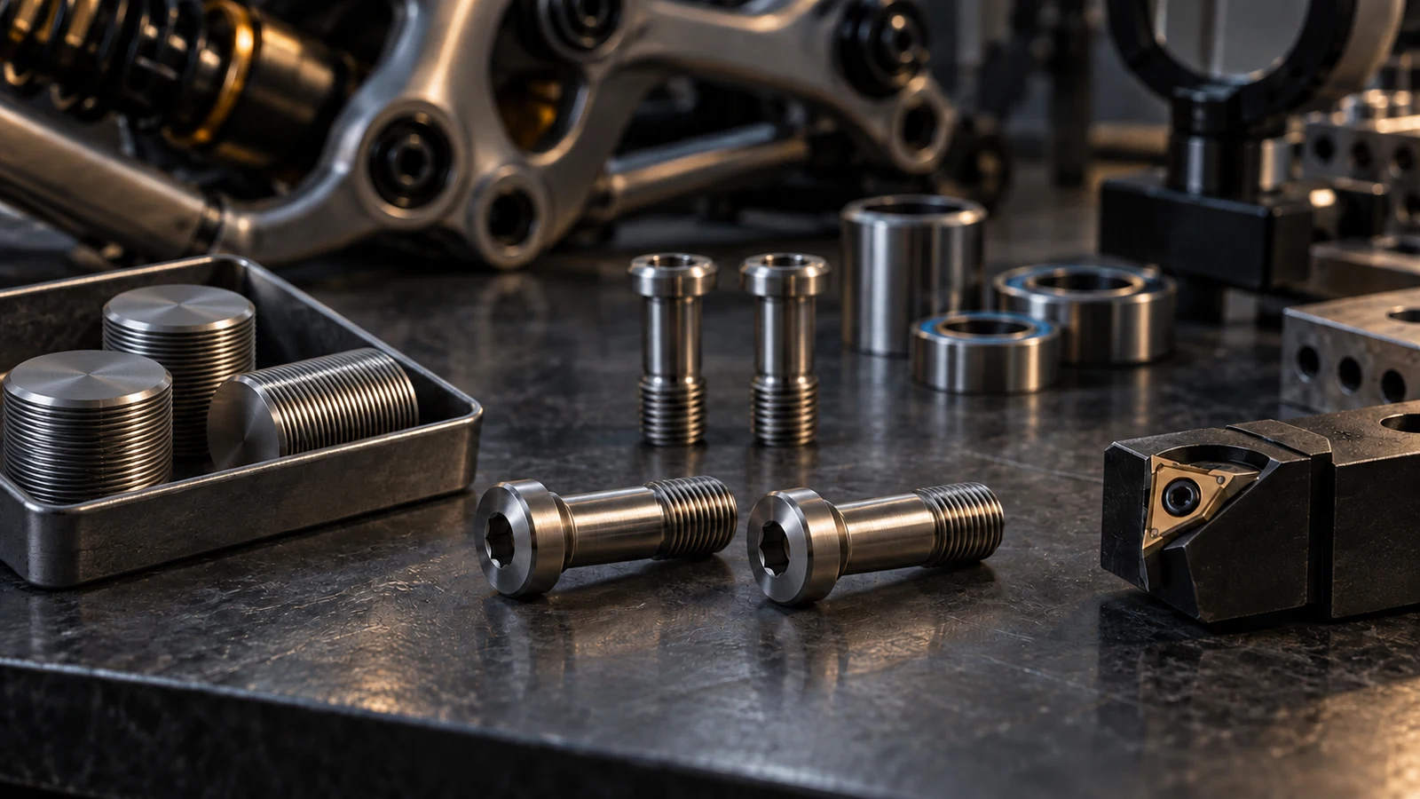
Hero: concept illustration of example hardware and its application. It is not a factory photograph, tested component or approved production geometry.
Understand the mechanism without assigning every TC4 thread a benefit
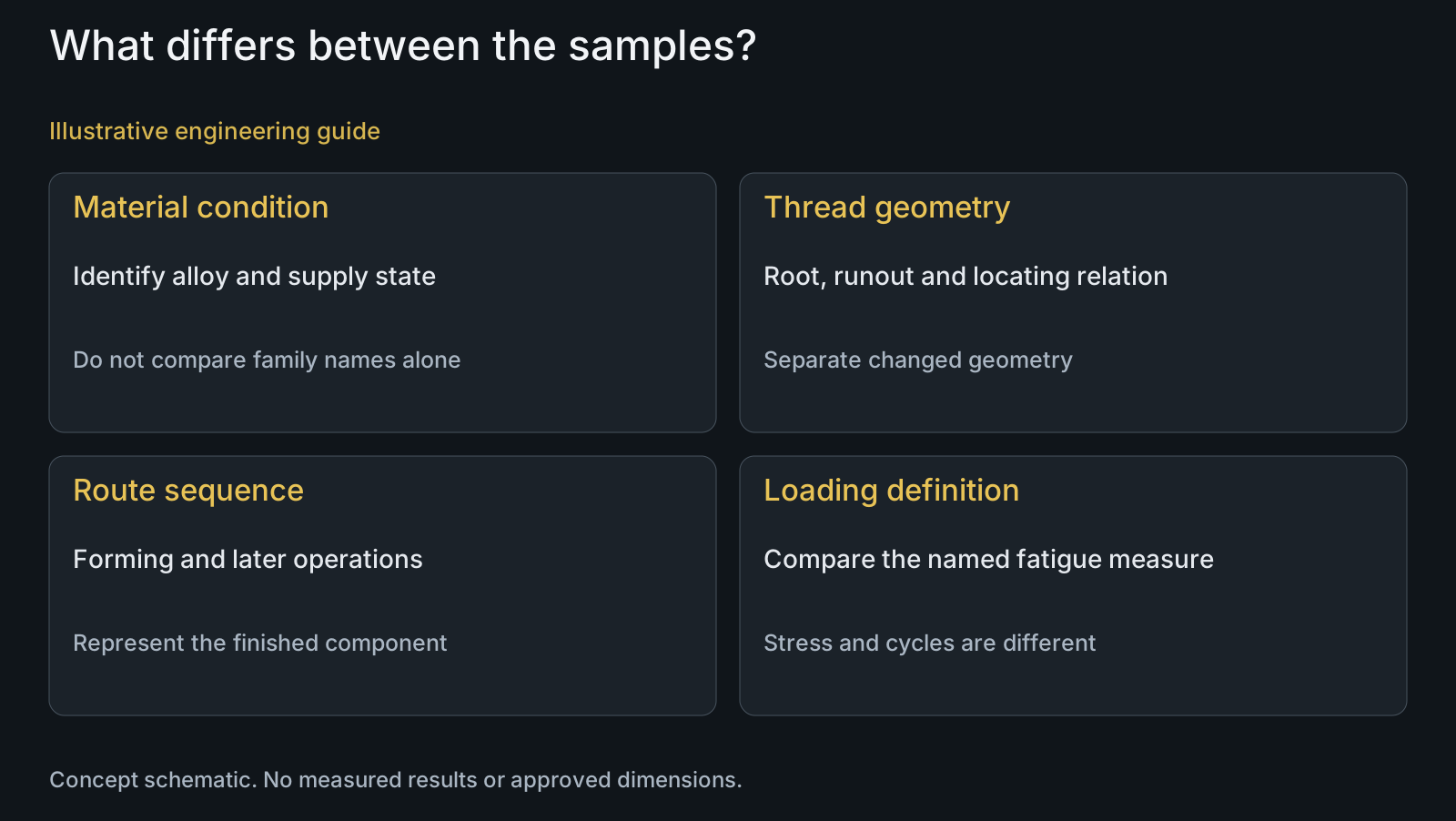
Cutting creates the thread by material removal; rolling forms the prepared blank by displacement. The general fatigue rationale is associated with the resulting root surface and residual-stress condition. NASA's Fastener Design Manual discusses favorable compressive surface stresses from cold rolling. It supplies a mechanism, not a TC4 pivot improvement percentage.
Treat that mechanism as a reason to investigate the route, not permission to assume that the desired condition exists in every delivered bolt. Identify the specified titanium alloy, product form and material condition at thread formation. A titanium family name alone does not define how the prepared blank responds to the proposed operation.
A controlled cut thread remains a possible solution when its geometry, surface and application requirements are satisfied. Do not reject it solely because another route is called rolled. Conversely, a rolled thread that misses the required profile or runout is not acceptable merely because rolling is associated with a favorable mechanism.
Establish comparable finished geometry before comparing the process
The control specimen needs more than matching nominal diameter and pitch. Compare root geometry, minor and pitch diameters, runout, thread length, shoulder transition and alignment to the locating features. State whether these are held comparable or intentionally changed; otherwise the experiment compares more than the thread-forming route.
The author-posted abstract of Armentia and colleagues' prosthetic-screw study reports that the rolled profile did not accurately reproduce the intended geometry despite a favorable fatigue comparison. The useful lesson here is to inspect the profile independently. Dental screws and their test arrangement are not validation of bicycle pivot hardware.
A supplier's actual rolling approach also needs suitable access near the shoulder and relief. Landis's thread-rolling documentation highlights this geometry consideration for its tooling. Do not copy its tool settings or material limits into a universal titanium requirement; review the proposed equipment and component instead.
| Comparison item | What must be identified | Confounding risk | Useful verification |
|---|---|---|---|
| Material condition | Specified alloy, form and condition at formation | A material change is attributed to rolling | Relevant supply and route records |
| Finished thread geometry | Root, profile, diameters, runout and alignment | Different geometry is called a process-only comparison | Feature and profile assessment beyond a process label |
| Manufacturing sequence | Thread formation and subsequent operations | Intermediate condition is treated as delivered condition | Identify the complete route represented by specimens |
| Fatigue strength measure | Stress quantity at a stated endpoint and conditions | Stress improvement is relabeled as a life percentage | Read the actual measure and its comparison basis |
| Cycle-life measure | Exposure under defined load and stopping rules | Surviving observations become exact failure lives | Preserve represented individual outcomes and endpoints |
| Pivot application | Receiver, support and initial assembly | Thread or dental-specimen evidence becomes bicycle approval | Application-matched assessment separate from thread fit |
Keep route sequence attached to the represented condition
Identify when the thread is formed relative to any heat treatment, cleaning and final finish. Two bolts described as rolled can represent different production sequences. If the claimed advantage depends on a particular root or surface state, the supplied route and any later processing must be part of the comparison rather than an omitted purchasing detail.
Ask what evidence describes the finished component after the complete route. A result from an intermediate blank does not automatically characterize the coated, cleaned or subsequently processed bolt. Where residual stress is used to explain a result, distinguish an actual relevant measurement from an assumption based only on process terminology.
PremFixer's confirmed manufacturing scope includes thread rolling and CNC operations, but that does not mean every titanium pivot uses one route or one sequence. The controlled drawing, material condition, geometry and agreed supplied scope determine the proposal. No universal all-titanium rolling policy or in-house fatigue laboratory is claimed here.
Define whether the claimed improvement concerns stress or cycles
A fatigue-strength comparison at a stated cycle endpoint and a cycle-life comparison at a fixed loading condition are not the same measure. State the plotted or reported quantity before quoting any percentage. Also identify loading mode, stress definitions, mean or ratio condition, initial assembly, failure criterion and stopping rule.
If the routes differ in material condition, root geometry or supported assembly, describe those differences explicitly. The result may still be useful as a finished-configuration comparison, but it cannot be attributed solely to rolling. Keep failed and surviving observations distinguishable; the titanium fatigue-life guide addresses that endpoint issue in detail.
A component result still needs an appropriate connection to the receiver, sleeve support and application loading. Thread gauging, material certification and assembly-fit evidence answer their respective questions; none alone supplies fatigue-life evidence. Do not convert a specimen result into riding years or extend it to an unrepresented design revision.
Illustrative review: isolate the process or label the changed configuration
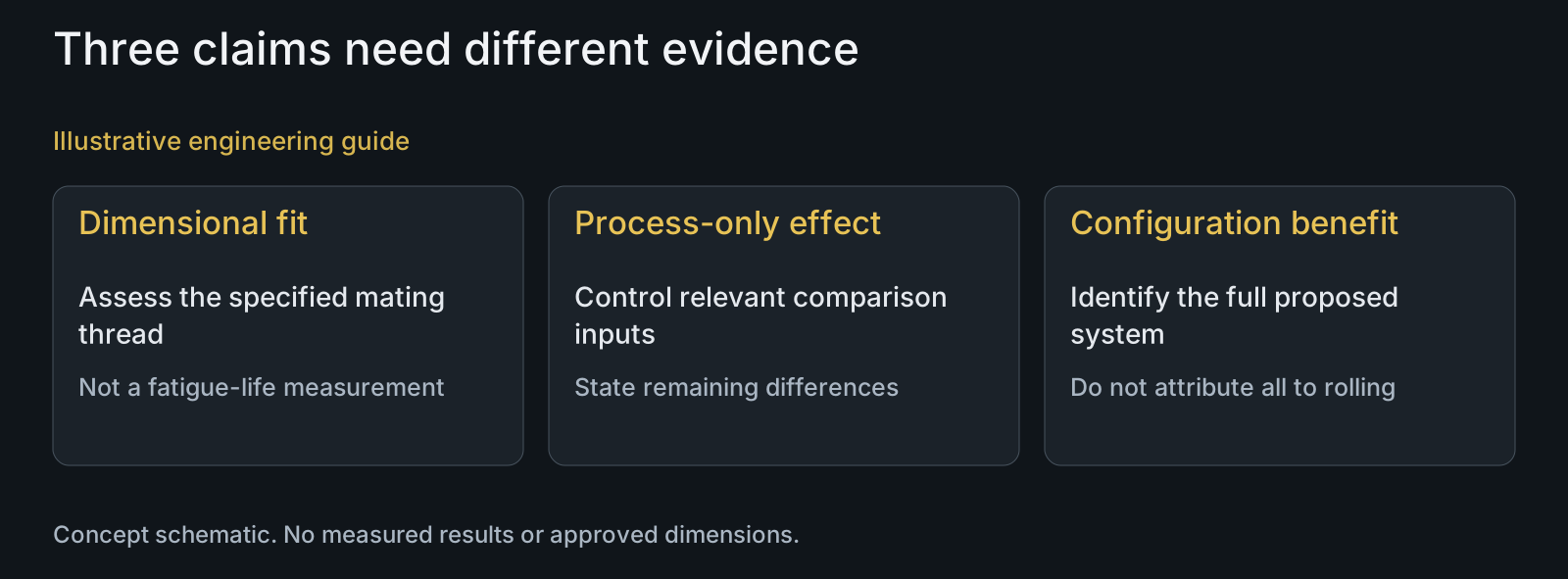
Illustrative engineering example: assume an OEM requests cut and rolled TC4 pivot samples for comparison. The rolled proposal also changes the thread-root profile and runout position. Both sample sets could meet the nominal diameter and pitch, but no fatigue tests have been performed.
The review chooses between two legitimate questions. To isolate the manufacturing-route effect, the team must establish the intended comparable geometry and conditions. To compare complete proposed configurations, it may retain the differences but report the result as a configuration comparison. Neither approach justifies attributing every later difference to rolling alone.
The RFQ can request identification of the supplied route, finished profile and agreed comparison inputs before samples are made. The broader cut-versus-rolled guide covers general process selection; this example focuses on interpreting a TC4 comparison. It contains no manufactured samples, stress values, measured improvement or approved fatigue outcome.
Questions buyers need to confirm
Are cut TC4 pivot threads automatically unacceptable?
No. Evaluate the specified geometry, surface, complete route and required application evidence. A process preference does not replace those requirements, and a controlled cut route can be a valid proposal.
Can rolled titanium threads be advertised with a fixed fifty-percent benefit?
Not without a defined supporting comparison. Identify whether the figure concerns stress or cycle life and preserve the represented conditions. No universal percentage for PremFixer TC4 pivots is established here.
Does matching nominal diameter and pitch make two test groups comparable?
Not by itself. Root profile, runout, shoulder relationship, material condition and finished surface can also differ. Control relevant inputs for a process-only comparison or disclose them in a complete-configuration comparison.
Does a passed thread gauge prove the rolling fatigue benefit?
No. It addresses the dimensional requirements covered by that inspection. Profile, surface condition and fatigue response need the relevant additional evidence; one fit result cannot answer every performance question.
Must rolling occur at one universal point in every TC4 route?
No universal sequence is prescribed here. Specify the material condition and proposed order of forming, thermal and finishing operations. Assess the condition actually represented by the supplied part and comparison rather than borrowing another alloy's process rule.
What should accompany a rolled-versus-cut sample RFQ?
Provide the controlled TC4 specification, bolt and receiver drawings, root and runout requirements, finish, proposed routes and quantities. State whether you need an isolated process comparison or a full-configuration comparison, with defined load, endpoint and required evidence.
Technical references and scope
NASA: Fastener Design Manual, RP-1228. General cold-rolling and compressive surface-stress mechanism. Historical guidance is not a TC4 improvement percentage, current drawing standard or bicycle qualification.
Armentia et al.: Rolled versus cut prosthetic-screw study abstract. Author-posted abstract identifies profile reproduction as a separate issue in its dental-screw comparison. No multiplier, static result or test method is transferred to a pivot.
Landis: Thread-rolling documentation. Tool-specific shoulder and relief access considerations. No equipment ownership, operating settings or universal titanium forming limit inferred.
Explore related component, material and sourcing decisions in the customer decision knowledge center. For a drawing review, use the Drawing/BOM RFQ path.
Set up a meaningful TC4 thread-route comparison
Send the drawing or STEP file, material condition, thread-root and runout requirements, receiver details and proposed finished routes. Define the comparison measure and represented loading if fatigue evidence is required. PremFixer will review sample manufacturing and route feasibility; test interpretation and application release remain tied to the actual agreed assessment.
Discuss the drawing and BOM