

A purchasing shortcut has become surprisingly common in high-end bicycle hardware: cut threads are treated as ordinary, while rolled threads are treated as proof of superior quality.
There is a sound engineering mechanism behind the interest in thread rolling. There is also a serious problem with turning that mechanism into a purchasing badge.
Cutting and rolling create a thread in different ways. Those routes can produce different root surfaces, near-surface hardness distributions and residual-stress states. Under suitable, controlled conditions, rolling can improve fatigue behaviour. But none of that tells us, by itself, whether a finished mountain-bike pivot bolt has the right geometry, whether its thread fits the real receiver, whether later processing preserved the intended surface condition, or whether the complete joint survives its required load spectrum.
The practical question is therefore not “Which process sounds more premium?” It is “Which controlled route produces the required geometry and verified performance for this joint?”
1. Define the joint before selecting the thread process
A pivot fastener is not only a threaded cylinder. Depending on the architecture, it may include a low-profile head, an internal drive, an under-head transition, a long smooth shoulder, a runout and a short terminal thread. Each region has a different functional role.
In many pivot arrangements, the smooth shoulder occupies the bearing, spacer or shear span. The terminal thread closes the stack through a nut, insert, threaded axle or frame-side receiver. The exact arrangement belongs to the assembly drawing, not to a generic bolt convention.
This matters because the first thread and the runout are geometric stress-concentration regions. If the runout enters a bearing seat, if a thread flank becomes the unintended support surface, or if the receiver does not provide the required engagement and seating condition, changing the thread from cut to rolled does not repair the load path.
Start the RFQ with functional geometry: datums, shoulder diameter and length, transition radii, runout location, thread form and class, receiver definition, finish allowance and assembly stack. Only then does the forming-route decision have enough context to be useful.
2. What cutting and rolling actually change
A cut or machined thread is produced by removing material. A rolled thread is cold formed by hardened dies that plastically displace a prepared blank into the thread profile. A CNC-turned pivot bolt with a subsequently rolled terminal thread is therefore not a contradiction: turning can establish the head, datums and shoulder, while another controlled operation forms the thread.
Rolling can create a smooth root surface, local work hardening and a compressive residual-stress field near the root. These conditions can be favourable because fatigue cracks often initiate at a surface or geometric stress concentration. NASA’s Fastener Design Manual describes the fatigue benefit associated with rolled threads and favourable compressive stress, while also treating fastener design as a system of material, geometry, manufacture and installation—not a single-process claim.
The word can is essential. The outcome depends on the alloy and condition, prepared blank diameter, thread form, die geometry, machine arrangement, pressure or penetration history, lubrication, number of blank revolutions, tool condition and any process that follows. Rolling is a process window, not a binary property.
Cutting also deserves more precise language. “Cut thread” can refer to different machining routes and tool strategies. A controlled cut thread with the required profile, surface condition and runout may be entirely appropriate. A rolled thread produced from the wrong blank or worn tooling may fail geometry or surface requirements despite carrying the more attractive label.
3. Read fatigue data as a test result, not a multiplier
The accompanying chart uses one carefully bounded comparison published in 2025. The study evaluated cylindrical M12 specimens made from 42CrMo4+QT under cyclic tensile loading at constant mean stress. The reported fatigue-strength values were 45.1 MPa for cut threads, 113.8 MPa for rolled threads and 71.1 MPa for deep-rolled threads.
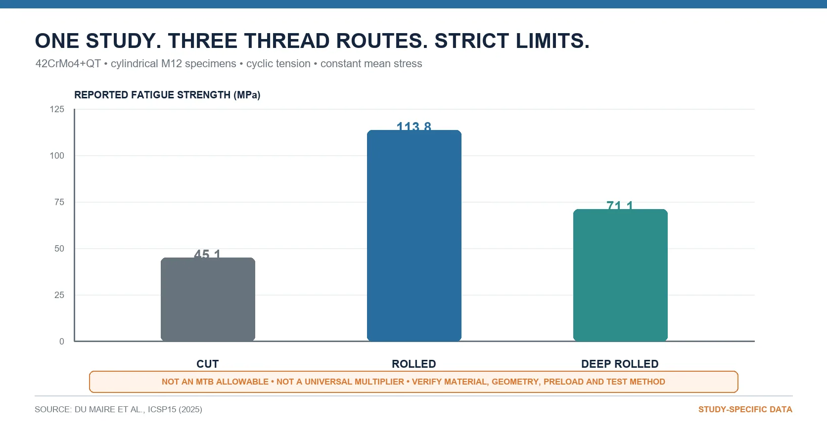
Those values demonstrate that fabrication route can matter in a defined test. They do not establish a universal improvement percentage. They are not an allowable for a bicycle drawing, and they do not predict the life of an unspecified titanium or steel pivot bolt. The specimens, material condition, nominal thread, loading mode and constant-mean-stress condition must travel with the numbers every time they are shown.
The third result is also instructive. In that study, the value labelled “deep rolled” did not sit above the ordinary rolled result. That alone should discourage a simple ranking in which more processing automatically means more fatigue strength. The response belongs to the studied route and specimen.
A second published comparison reached a similarly conditional conclusion in another application. A 2021 study examined Ti-6Al-4V ELI M1.8 prosthetic screws in a defined dental-implant restoration assembly and test method. The rolled group showed higher compressive residual stress and a regression fatigue life of about nine times the cut group. Yet static failure strength was statistically similar, and the rolled thread profile did not accurately reproduce the intended geometry.
That is valuable evidence for those screws and that test. It is not a nine-times life claim for an MTB pivot bolt. Together, the two studies support a narrower and more useful conclusion: thread manufacture can materially affect fatigue response, but the magnitude and even the balance of benefits depend on the complete test and production conditions.
4. Sequence is part of the process specification
“Rolled thread” still leaves a major question unanswered: rolled when?
Research on high-strength steel fasteners shows that rolling before and after heat treatment can produce different thread-root residual-stress states and fatigue responses. An older JSME investigation studied quenched-and-tempered M10 and M10×1.25 steel bolts and reported different residual-stress outcomes for the two sequences. Separate ASTM work on high-strength bolts examined thread profile, preload and rolling sequence together; the response did not support a universal rule that one sequence is always best.
Rolling a softer blank before heat treatment may reduce forming load, but the later thermal cycle can change dimensions and the residual-stress state. Rolling after heat treatment creates a different forming and tooling problem. The correct route depends on material condition, thread geometry, equipment capability and qualified results.
Finishing belongs in the same route review. A coating can change fit and friction. For susceptible high-strength steels, coating and cleaning may introduce a separate hydrogen-embrittlement control question. ASTM F519 provides a defined process-evaluation framework, but invoking that method is not automatic proof for a target pivot bolt. The applicable material, specimen, process and acceptance plan still have to be established.
The released route should therefore state the order of turning, heat treatment, thread formation, cleaning, finishing and final inspection. Naming only the most marketable operation leaves the highest-risk interfaces uncontrolled.
5. A practical cut-versus-rolled decision review
An engineering or purchasing team can make the choice more disciplined by reviewing six questions.
Is the load path defined?
Confirm where the shoulder supports bearing inner races or spacers, where clamp load closes the stack, where the runout sits and what component receives the thread. If those answers are missing, pause the process debate and complete the joint definition.
Is the material condition defined and compatible?
Specify alloy, product form, strength or hardness condition, heat/lot traceability and the stage at which the thread will be formed. “Steel” or “titanium” is not enough to establish rollability or a process window.
Is the required geometry producible and measurable?
Review blank diameter, thread form, pitch, class, root and crest requirements, runout, coaxiality to the shoulder, finish allowance and receiver fit. ISO 1502 provides a framework for metric thread gauges and gauging, but the drawing and invoked requirements still define acceptance.
Is the full sequence controlled?
Identify the actual cutting tool or rolling arrangement, key setup controls, lubrication, die or tool-life management, heat-treatment order, cleaning and finish. A supplier should be able to describe the real route without substituting a generic process photograph.
Does inspection address the likely failure modes?
Pass/fail thread gauging is necessary in many programmes, but it is not the entire release plan. The plan may also need shoulder and runout measurement, surface-discontinuity controls, hardness or case-condition evidence, coating records and receiver-fit verification. The required evidence must follow the drawing and risk assessment.
What level of validation does the claim require?
Process evidence shows that a route is controlled. Fastener testing addresses a defined fastener under a defined load case. Pivot-subassembly or frame validation adds the real receiver, spacer and bearing stack, installation method, linkage stiffness and system load path. These levels answer different questions and should not be collapsed into one claim.
6. What “high-end” should mean on an RFQ
If an OEM requires rolling, the RFQ should say more than “rolled thread.” It should connect the requirement to the controlled blank, material condition, thread geometry, route sequence, inspection plan and change-control expectations. If the route is left open to the supplier, the RFQ should define functional and verification requirements clearly enough for cut and rolled proposals to be compared on evidence.
A useful supplier discussion covers:
- the controlled material and incoming condition;
- functional shoulder, runout and receiver geometry;
- prepared blank and thread-forming route;
- heat-treatment and finishing sequence;
- thread and feature inspection methods;
- tool-life, nonconformance and process-change controls;
- representative joint conditions for any required validation.
ISO 898-1 is useful within its stated scope for mechanical properties of carbon and alloy steel fasteners, but it explicitly does not specify fatigue resistance. A property class, material callout or process name cannot serve as a fatigue release by itself.
Likewise, ISO 4210 bicycle and frame/fork requirements provide system and subassembly context. They do not turn a thread-process study into proof that an individual bolt will survive an undefined Enduro or downhill impact. Any performance statement must stop at the envelope of the actual evidence.
7. The decision rule
Choose rolling when the geometry, material condition, quantity, process window and validation evidence make it the right route. Choose cutting when it better satisfies the geometry, access, volume or controlled-production requirements. In either case, release the result against the drawing and the real joint—not against a manufacturing stereotype.
A controlled cut thread can be the correct high-end solution. An uncontrolled rolled thread can be the wrong one.
The most defensible definition of premium hardware is not a process word. It is a traceable chain:
functional joint → defined material and geometry → qualified route → measurable output → application-matched evidence
That is what gives an engineer confidence, gives a quality team something to audit and gives a purchasing manager a basis for comparing suppliers without buying a slogan.
Author & Contact
Kang Wang
Senior Product & Technical Lead | Bicycle & Motorcycle Division
PremFixer (Guangdong Pinshang Hardware Co., Ltd.)
Website: https://premfixercnc.com/
WhatsApp: +86 15766506531
References
- ASM International, “Thread Rolling,” ASM Handbook, Volume 14A: Metalworking—Bulk Forming: https://doi.org/10.31399/asm.hb.v14a.a0004012
- R. T. Barrett, Fastener Design Manual, NASA Reference Publication 1228: https://ntrs.nasa.gov/api/citations/19900009424/downloads/19900009424.pdf
- P. du Maire et al., “Investigations on the Fatigue Strength of Threads Produced by Different Fabrication Techniques,” 15th International Conference on Shot Peening, 2025: https://docs.lib.purdue.edu/icsp15/papers/fatigue1/2/
- M. Armentia et al., “Fatigue performance of prosthetic screws used in dental implant restorations: Rolled versus cut threads,” Journal of Prosthetic Dentistry, 2021: https://doi.org/10.1016/j.prosdent.2021.06.035
- I. Yoshimoto, “The Effect of the Thread Rolling Conditions on the Fatigue Strength of the Rolled Screw Threads,” 1961: https://doi.org/10.1299/jsme1958.4.406
- I. Yoshimoto, K. Maruyama and Y. Yamada, “Prediction of Fatigue Strength of Bolt-Nut Joints Based on Residual Stress,” 1984: https://doi.org/10.1299/kikaia.50.717
- Horn and Stephens, ASTM STP45329S, high-strength bolt threads rolled before and after heat treatment: https://store.astm.org/stp45329s.html
- ISO 1502:1996, ISO general-purpose metric screw threads—Gauges and gauging: https://www.iso.org/standard/6092.html
- ISO 898-1:2013, Mechanical properties of fasteners made of carbon steel and alloy steel: https://www.iso.org/standard/60610.html
- ASTM F519-23, Standard Test Method for Mechanical Hydrogen Embrittlement Evaluation of Plating/Coating Processes and Service Environments: https://store.astm.org/standards/f519
- NASA-STD-5020B, Requirements for Threaded Fastening Systems in Spaceflight Hardware: https://standards.nasa.gov/standard/NASA/NASA-STD-5020
- ISO 4210-2:2023 and ISO 4210-6:2023, bicycle requirements and frame/fork test methods: https://www.iso.org/standard/78077.html and https://www.iso.org/standard/78081.html
- Related PremFixer evidence package,
output/2026-08-10/04_深度文章.md
Claim-to-Source Map
| Claim used in this article | Source | Evidence type | Boundary |
|---|---|---|---|
| Cutting removes material; rolling cold forms a prepared blank by displacement. | ASM Handbook, “Thread Rolling” | Authoritative technical reference | Process definition only; no finished-part performance claim. |
| Rolling can create favourable root-surface and compressive residual-stress conditions for fatigue resistance. | NASA RP-1228; ASM Handbook | Government technical guidance / authoritative reference | Conditional mechanism; does not prove a target pivot bolt. |
| The 2025 study reported 45.1 MPa cut, 113.8 MPa rolled and 71.1 MPa deep rolled. | du Maire et al., 2025 | Primary conference paper | 42CrMo4+QT cylindrical M12 specimens, cyclic tensile loading at constant mean stress; not an MTB allowable or universal multiplier. |
| The Ti-6Al-4V ELI study reported about nine-times regression fatigue life for rolled screws, similar static strength and imperfect profile reproduction. | Armentia et al., 2021 | Peer-reviewed primary study | M1.8 prosthetic screws in the study’s dental-implant restoration assembly and test method; not transferable as a bicycle life multiplier. |
| Rolling conditions and heat-treatment order can change root residual stress and fatigue response. | Yoshimoto, 1961; Yoshimoto et al., 1984; ASTM STP45329S | Primary technical studies | Specific steels, thread sizes/profiles and test conditions; no universal sequence rule. |
| ISO 1502 supplies a metric gauging framework. | ISO 1502 | Standard | Drawing, invoked edition and acceptance plan still control the target part. |
| ISO 898-1 does not specify fatigue resistance. | ISO 898-1 | Standard scope statement | Does not diminish the properties that ISO 898-1 does cover. |
| Coating of susceptible high-strength steel may require separate hydrogen-embrittlement process evaluation. | ASTM F519 | Standard test method | Applicability and acceptance plan must be defined; not proof for an unspecified bolt. |
| Thread and fastener verification should reflect the actual hardware, receiver and installation process. | NASA-STD-5020B | Government standard / engineering principle | Used as a verification principle; no claim that bicycle hardware is NASA-compliant. |
| Process evidence, fastener testing and bicycle-system validation answer different questions. | NASA-STD-5020B; ISO 4210-2/-6; cited studies | Engineering synthesis | Explicit inference; no Enduro/DH performance guarantee. |
Suggested Hashtags
#ThreadRolling #FastenerEngineering #MTBEngineering #CNCManufacturing #FatigueDesign #SupplierQuality #PivotBolts
Start With the Actual Interface
Send the drawing or sample and the application context so the discussion stays tied to the approved part and its joint.
Send a Drawing or Sample