
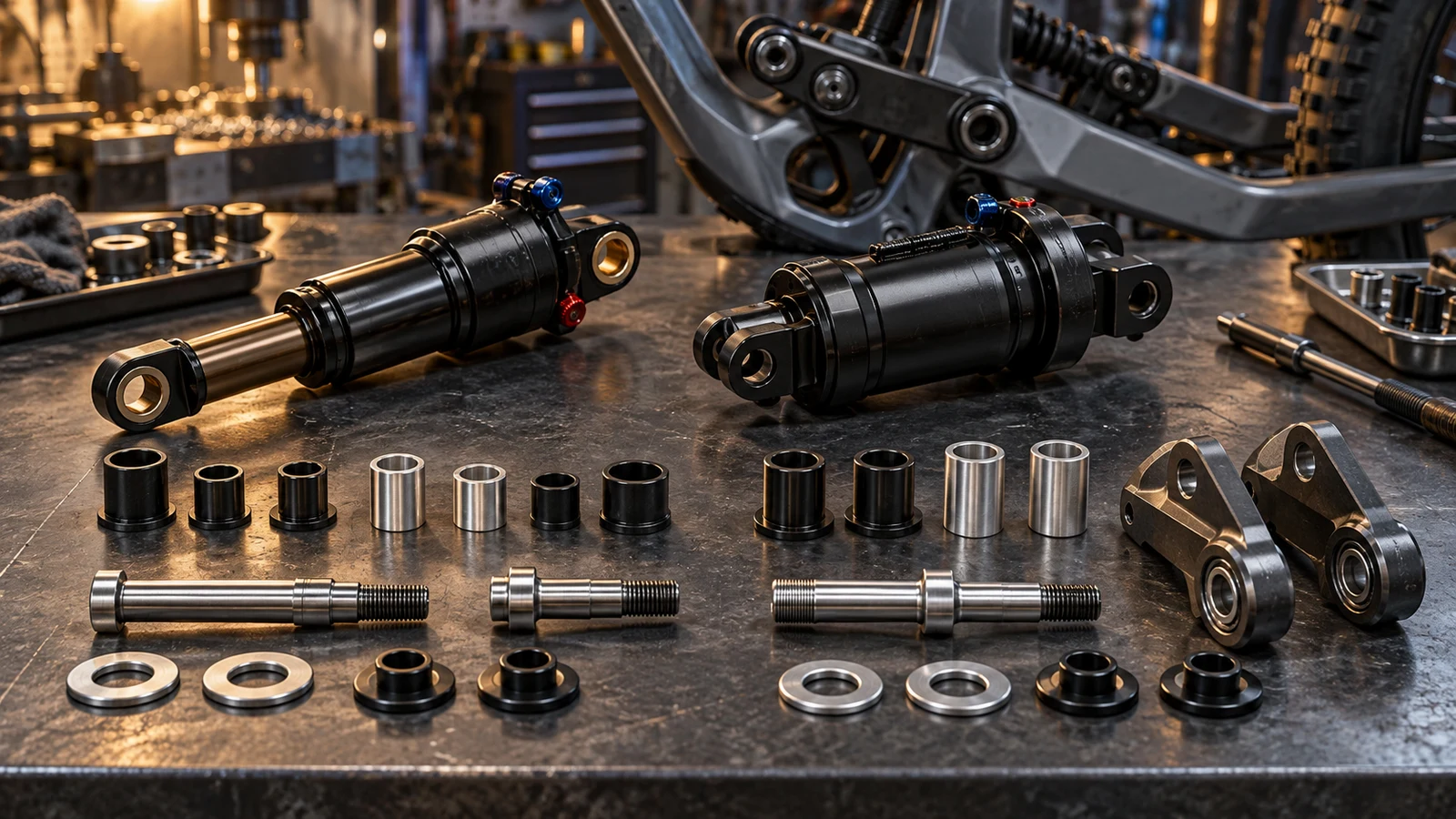
Matching nominal bolt diameter does not make rear-shock mounting hardware interchangeable. For an OEM selecting custom shock mounting bolts and spacers, identify the exact shock, frame revision and upper or lower mount first. Standard eyelet, trunnion and bearing-mount arrangements can require different components and contacts. Mounting width, shoulder geometry, receiver and the specified supplied kit must agree with that arrangement; eye-to-eye length alone does not define them. PremFixer can review drawing-defined hardware manufacture, but a similar catalog size is not evidence of fit. Keep the component supply decision separate from approval of the shock's complete installation and movement envelope.
Hero: concept illustration of example hardware and its application. It is not a factory photograph, tested component or approved production geometry.
Identify each mount before choosing a hardware family
Record the shock identity, frame configuration and mounting position. Treat upper and lower connections as separate entries in the assembly definition, even when the same shock links them. Identify whether each connection uses an eyelet, trunnion or specified bearing arrangement.
SRAM's RockShox fitment guidance distinguishes standard and trunnion eyelets and states that mounting hardware specifications depend on the frame design. It also discusses bearing-mount alternatives. These are reasons to identify the represented architecture, not permission to convert between styles or assume one generic reducer kit will work.
Include the applicable shock and frame documents in the inquiry. The rear-shock torque reference guide addresses finding the governing installation instruction; this article addresses the geometry and supplied parts that instruction must correspond to. A fitment explanation is not a universal wrench setting.
Keep shock length, hardware width and bolt length distinct
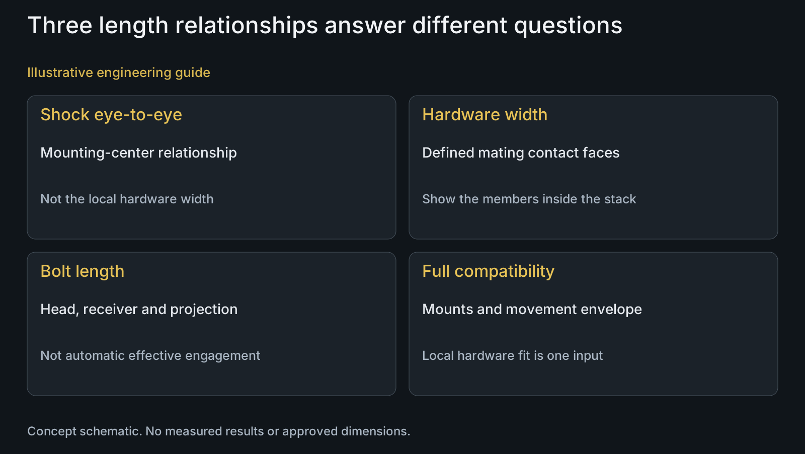
Eye-to-eye length locates the shock mounting centers, whereas hardware width concerns the local interface at a mount. The bolt's total length and effective engagement are further relationships. Label each explicitly rather than placing one unexplained length beside a shock photograph.
Show the distance between the intended mating contacts and identify the components that occupy it. In an eyelet arrangement, identify the specified bushing or bearing and any hardware that adapts the eyelet to the frame. Do not infer the final width from the visible shock body or the bolt alone.
Engineering analysis: equal overall widths can conceal different contact positions or component distributions. A package can occupy the available space while failing to establish the intended shoulder or ring contacts. Use the stack-up guide for that distinction, not a universal shock clearance value.
| Input or arrangement | What to establish | Risk of a shortcut | Verification basis |
|---|---|---|---|
| Standard eyelet | Specified bushing/bearing and adapting hardware | Universal reducer assumption | Applicable shock and frame definition |
| Trunnion connection | Frame-specified direct mounting relationship | Copying a standard-eyelet kit | Named parts and represented mount |
| Bearing-mount alternative | Bearing arrangement and approval scope | Same nominal width means conversion approved | Manufacturer and OEM compatibility decision |
| Matching hardware width | Actual contact faces and included members | Hidden sleeve or shoulder omitted | Section and local stack comparison |
| Matching bolt diameter | Receiver, head contact and effective engagement | Thread entry proves fit | Complete component and mating geometry |
| Custom kit quotation | Supplied versus reference-only components | Component price implies whole-shock approval | BOM, revisions and explicit acceptance scope |
Map the bolt receiver and the moving interface
Identify which part receives the thread and where the bolt head or shoulder bears. Mark the threaded and unthreaded regions relative to the actual mounting members. A bolt that enters the receiver may still have an unresolved bottoming, contact or engagement relationship.
Distinguish what is intended to move from what is clamped or located. Depending on the architecture, motion may occur within a bushing or bearing rather than by allowing an unspecified bolt contact to slip. Do not diagnose high-frequency fretting merely from the application name or assume lubricant changes will resolve it.
Discuss effective thread engagement using the actual receiver and contact stack. Preserve the manufacturer's instruction for the represented hardware. If a material, coating or supplied locking condition changes, identify that change rather than applying an improvised torque correction.
Separate the local hardware fit from whole-shock compatibility
A defined mounting bolt and spacer set answers a local interface question. It does not alone establish the shock body's clearance, travel relationship or suitability in the frame. Those require the responsible product team's shock and frame compatibility assessment.
SRAM's guidance treats shock dimensions and clearance through suspension movement as compatibility questions in addition to mounting hardware. Use the applicable manufacturer's procedure and authority for the represented product; no new installation operation is prescribed here.
If an OEM changes the shock or mount arrangement, list both the local hardware changes and the separate system questions. The full-suspension solution describes the application context, while a component quotation remains limited to the agreed drawings and supply boundary.
Define which hardware is custom and which is specified elsewhere
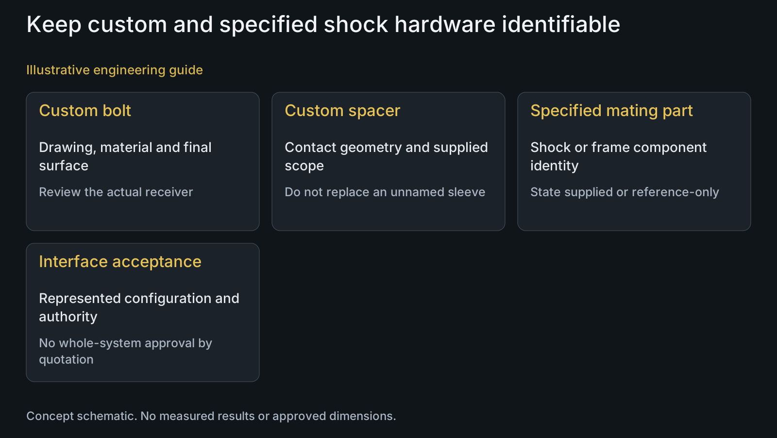
List custom bolts and spacers separately from manufacturer-specified bearings, bushings or other parts. Identify their drawings, quantities and revisions, and mark whether each is supplied, customer-provided or reference-only. A quoted spacer should not silently become an approved substitute for a specified shock component.
For each custom item, state material condition, final finish and the functional features to inspect. Review those through materials and CNC turning. Neither TC4 nor an anti-galling treatment is a universal shock-mount specification or evidence of validated durability.
Make inspection scope explicit: part dimensions and final surfaces, kit completeness, or an agreed represented-interface check. Describe the applicable mating parts if a check is requested. Manufacturing conformity does not certify the completed bicycle or authorize a change to an unrelated shock revision.
Review example: same diameter and width, different contacts
Illustrative engineering example: assume an OEM compares two proposed lower shock-hardware sets with the same nominal bolt diameter and stated overall width. One drawing locates against a specified internal sleeve; the other gives only exterior spacer dimensions. No measured installation or performance result is assumed.
The reviewer compares the contact stack, moving interface and receiver rather than declaring the sets interchangeable. It asks which faces establish the specified width and whether the sleeve is part of the supplied kit or a retained component. The unresolved relationship is visible even though the headline dimensions match.
The RFQ then identifies custom components and reference-only shock hardware, with the upper connection listed separately. The useful output is a complete local interface definition and an explicit compatibility boundary, not a claim that either proposal has passed a shock or bicycle test.
Questions buyers need to confirm
Is nominal diameter enough to order a shock-mount bolt?
No. Identify the exact mount and compare receiver, engagement, head or shoulder contact and surrounding stack. Include the shock and frame configuration. Matching diameter does not define the mount's width or required retention relationship.
Are eye-to-eye length and hardware width the same measurement?
No. Eye-to-eye describes the shock mounting-center relationship; hardware width describes a local mount interface. Bolt length is another input. Label their reference locations and provide the appropriate drawings rather than using one length as the entire hardware definition.
Can standard-eyelet hardware be reused at a trunnion mount?
Do not assume so. Identify the manufacturer-defined arrangement and required parts. Trunnion and standard mounts have different architectures; conversion requires a specific compatibility basis, not a shared nominal dimension or a generic hardware photograph.
Does a bolt-and-spacer fit establish whole-shock compatibility?
No. Local contact and fastening conformity do not resolve the shock's dimensions or clearance during suspension movement. Keep the responsible manufacturer's or OEM's complete compatibility assessment separate from the supplied hardware inspection.
Should every custom shock bolt use titanium and anti-galling coating?
No universal requirement is supported. Define the material condition, final contacts, receiver and approved assembly treatment for the represented component. A material or finish change needs an applicable acceptance basis rather than an application-wide prescription.
What should an OEM shock-hardware RFQ contain?
Send shock and frame identity, upper and lower mount sections, component drawings, STEP or represented samples and BOM quantities. Include width-defining contacts, bearing or bushing data, receiver and instructions. Mark custom, supplied and reference-only items and identify unresolved compatibility fields.
Technical references and scope
SRAM RockShox rear-suspension fitment. Standard/trunnion and bearing-mount distinctions, frame-defined mounting hardware, and separate shock-dimension/movement clearance questions. No universal size, torque or conversion permission.
Explore related component, material and sourcing decisions in the customer decision knowledge center. For a drawing review, use the Drawing/BOM RFQ path.
Quote the shock hardware against its actual mounting contacts
Send the shock and frame identification, upper/lower mount sections, bolt and spacer drawings, STEP or represented samples and BOM. Include mating bearing or bushing information, receiver, final material and finish, quantities and applicable instructions. PremFixer can review the custom component scope while whole-shock compatibility remains a separate product decision.
Discuss the drawing and BOM