
Suspension pivot hardware needs a joint-specific load and interface review, not a universal titanium specification. Identify whether the part supports a linkage pivot, shock attachment or another defined connection, then examine its support span, contacts, retention and intended movement. The buyer is deciding which geometry, material condition and manufacturing route can meet the actual component requirement. A changing suspension load does not automatically mean the same stress history at every bolt, and a material fatigue curve does not approve the assembled joint. Treat titanium, rolled threads and peening as options with defined scope and relevant evidence. Do not substitute a process list for the missing load and boundary conditions.
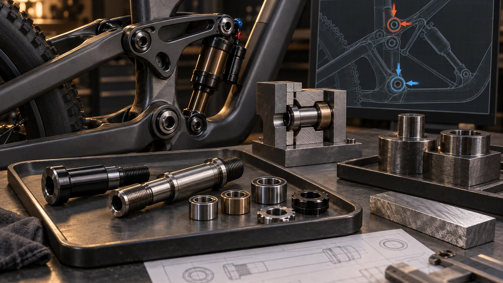
Hero: concept illustration of example hardware and its application. It is not a factory photograph, tested component or approved production geometry.
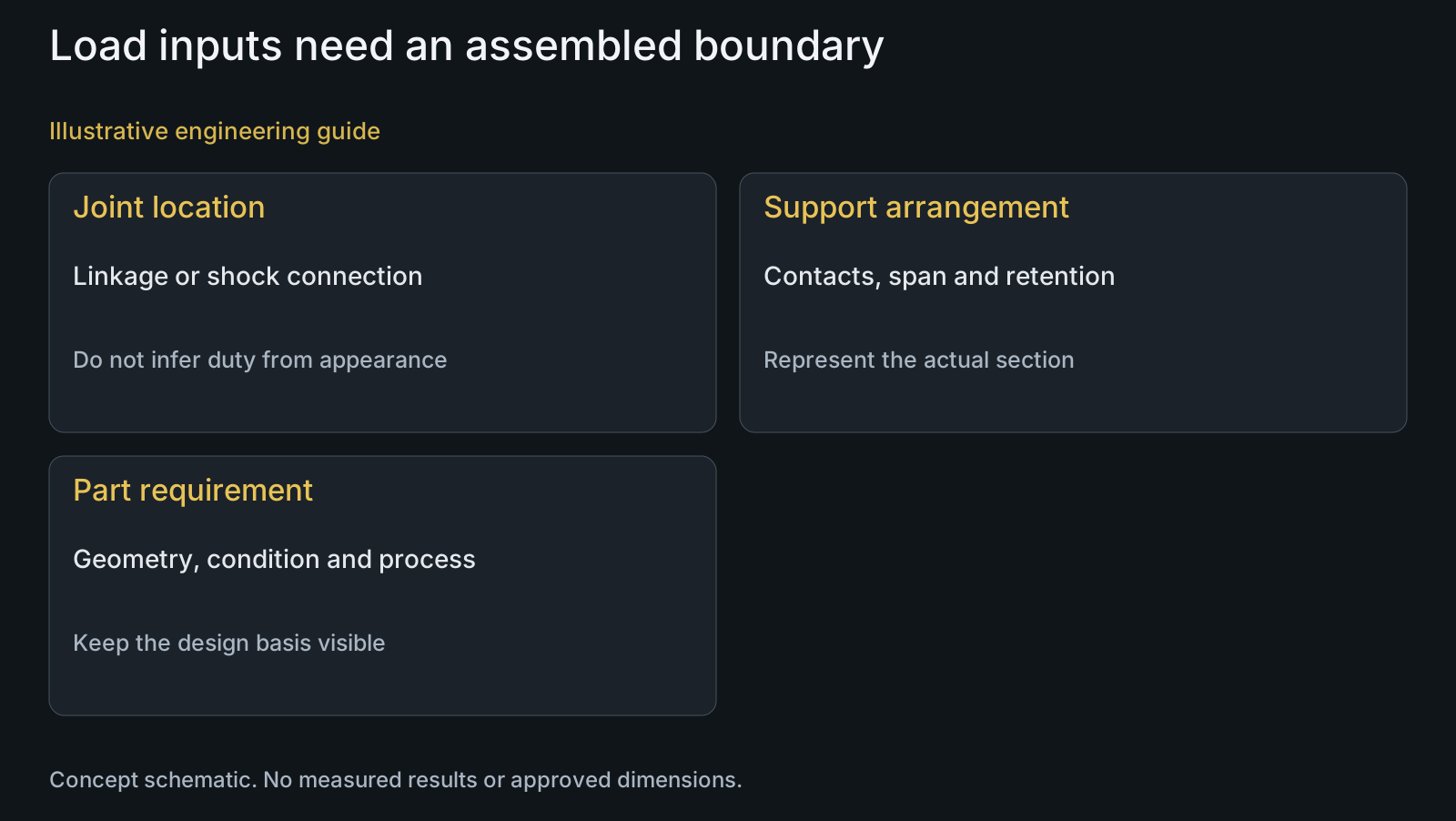
Name the joint and the source of its loading
A shock attachment and a linkage pivot can use similar-looking hardware while transferring force through different members. Identify the location in the suspension architecture, the supported component and the mating contacts. The name suspension bolt is too broad to establish its mechanical duty.
Request the relevant forces or analysis inputs, directions, operating positions and intended use conditions from the design owner. Separate a maximum-event question from a repeated-loading question. Do not invent a high-frequency cycle count from the fact that the bicycle has suspension.
Use the frame integration review to map locating and clamping contacts. This article carries the resulting support arrangement into material and process decisions. A load value without its application point, supports and assembly state is not a complete component input.
Review support geometry before comparing alloy names
Show the axle's supported regions, free span, shoulder transitions, bore and retaining thread in the assembled section. Identify where load enters and where reactions occur. A longer unsupported portion or changed contact can require renewed analysis even if the outer diameter and material name are unchanged.
Keep load transfer through the intended interfaces distinct from retention. A calculation for a simplified shear section does not automatically represent bending, thread engagement or a local transition. State the simplification and ask which relevant component features it leaves out.
For a proposed geometry change, compare both mechanical function and manufacturing access. An internal bore may affect the remaining section; a transition chosen for machining may affect an adjoining seat. Review these relationships against the actual design instead of asserting that hollow or solid hardware is always preferable.
| Proposal or evidence | Relevant condition | Risk of overextension | Review needed |
|---|---|---|---|
| Different alloy | Grade, condition and joint duty | Alloy name treated as approval | Material and component basis |
| Revised hollow section | Bore, transition and support span | Outer diameter treated as unchanged strength | Represented geometry and loading |
| Rolled retaining thread | Blank, material and thread region | Benefit assigned to unrelated shoulder | Route and final profile evidence |
| Specified peening | Surface, process and final interfaces | Undefined blast treated as fatigue guarantee | Controlled route and relevant evaluation |
| Material fatigue specimen | Geometry, surface and axial loading | Specimen result treated as joint life | Defined relation to service conditions |
| Assembly evaluation | Supports, retention and loading | One condition extended to all use | Design-owned represented scope |
Define material condition and process scope together
Specify the material standard, grade, supplied condition and required evidence, not just titanium or stainless. The materials overview helps frame available drawing-defined choices. A familiar alloy label cannot establish the final part's strength, contact behavior or suitability for an unreviewed joint.
CJWinter describes thread rolling as displacement of ductile material into a die-defined form rather than chip removal. That mechanism makes blank geometry, material condition, access and final thread inspection relevant. Its published improvement percentages are not adopted as predictions for PremFixer hardware.
If rolling is proposed, identify the thread region and process sequence to be evaluated. The resulting profile and specified acceptance still need confirmation. A rolled retaining thread cannot be assumed to resolve a concern located at a shoulder, bearing contact or frame receiver.
Do not add peening as an undefined fatigue guarantee
Peening is a candidate surface process, not an interchangeable word for every decorative blast finish. Ask which surface and fatigue question the proposal addresses, how the process is specified and how controlled seats or threads are protected and accepted afterward. Do not add it to a drawing without resolving those boundaries.
NASA's public abstract for a peening study examines particular steel and aluminum specimens with defined flaws and crack-growth conditions. It illustrates why the material, specimen and condition matter. Its results are not transferred to titanium bicycle pivots or quoted as a life improvement for an untested component.
Coordinate any specified route with the surface-treatment review. PremFixer's confirmed manufacturing and qualified-partner boundaries apply. No specific peening equipment, qualified recipe or successful suspension application is claimed here.
Match fatigue evidence to the question it represents
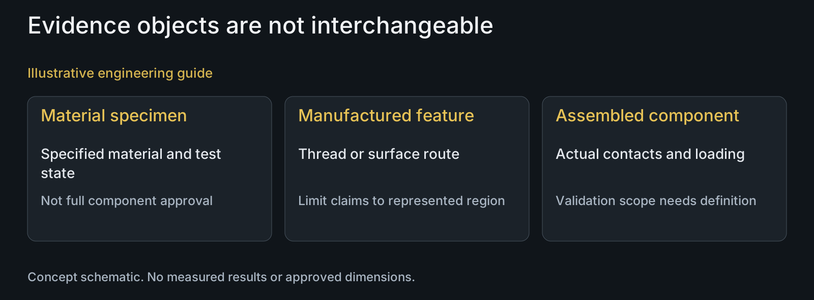
ASTM E466-21's public scope concerns force-controlled constant-amplitude axial fatigue specimens, not full-scale components or consumer products. It provides a useful evidence boundary: a specimen result may support analysis, but cannot be renamed an approved complete bicycle pivot result.
Compare the test object's material condition, geometry, surface and applied loading with the intended question. A plain coupon, threaded specimen and assembled hardware can establish different evidence. Retain load direction, support, retention and environmental assumptions when explaining how a result relates to the design.
If the actual concern is unknown, use the failure diagnostic map to separate competing mechanisms. Changing alloy after an unexplained fracture does not establish a cause or validate the replacement. Component and system acceptance remain with responsible design and validation parties.
Illustrative review: revised support spacing
Illustrative engineering example: assume a linkage redesign moves one support outward while retaining the proposed titanium axle material and outer diameter. The revised contacts and span have not yet been represented in analysis. No actual load, stress, test result or customer design is supplied.
The team compares the old and new assembled sections and requests the loading basis for the new arrangement. A material fatigue datasheet cannot account for the changed support by itself. Adding a rolled thread is a separate proposal, particularly if the suspected controlling region is a shoulder rather than the retaining thread.
The useful next decision is which geometry, manufactured state and evaluation would represent the revised joint. The example does not conclude that the new axle will fail or pass. It shows why unchanged alloy and diameter do not justify carrying forward a previous component assumption.
Questions buyers need to confirm
Does every suspension pivot need titanium, rolled threads and peening?
No. Review joint location, loads, support span, geometry, material condition and the controlling feature. Each proposed process must address a defined requirement and remain compatible with finished interfaces. No universal package is specified here.
Is a shock mounting bolt equivalent to a linkage pivot axle?
Not by appearance alone. Identify the members it supports, load application, bearing or bushing interfaces and retention arrangement. Those inputs can change the component duty even when the hardware looks similar or shares a nominal diameter.
Can a material fatigue curve establish pivot service life?
Not by itself. Compare the specimen geometry, surface state, loading and environment with the actual component and assembly. Explain the analysis connecting them and retain its limits; do not relabel material data as a validated bicycle joint result.
Can thread rolling solve a shoulder-related concern?
It cannot be assumed to. Identify the controlling region and mechanism first. A process applied to a retaining thread represents that region and route; a shoulder transition, support change or receiver issue may need a different design review.
Is cosmetic blasting equivalent to specified shot peening?
Do not assume equivalence. Provide the intended process specification, target surface, controlled parameters and final interface requirements. Appearance alone does not establish a fatigue-related surface state or an approved treatment route.
What inputs are needed for a suspension hardware RFQ?
Provide the assembly section, STEP and part drawing, joint location, mating BOM, material condition, finish, retention method and permitted load or use inputs. Add the evaluation question and prototype quantity so manufacturing proposals are assessed against a defined component need.
Technical references and scope
ASTM E466-21 public scope. Public description of constant-amplitude axial specimen testing and exclusion of full-scale components and consumer products. Detailed procedures and test parameters are not reproduced.
CJWinter, thread rolling process explanation. Manufacturer description of forming ductile material with dies rather than cutting. Advertised cost, strength and fatigue percentages are not transferred to this hardware.
NASA/TM-2001-210843 public research abstract. Primary abstract concerns peened steel and aluminum specimens with specified flaw and crack-growth conditions. No numerical result or material transfer to titanium bicycle pivots is made.
Explore related component, material and sourcing decisions in the customer decision knowledge center. For a drawing review, use the Drawing/BOM RFQ path.
Connect your suspension requirement to the hardware route
Send the joint section, drawings and STEP, mating BOM, material and finish specifications, intended conditions and available design load inputs through the Drawing/BOM RFQ path. PremFixer can review the manufacturability of defined axle, thread and spacer features; component life and system acceptance require the responsible design and validation process.
Discuss the drawing and BOM