

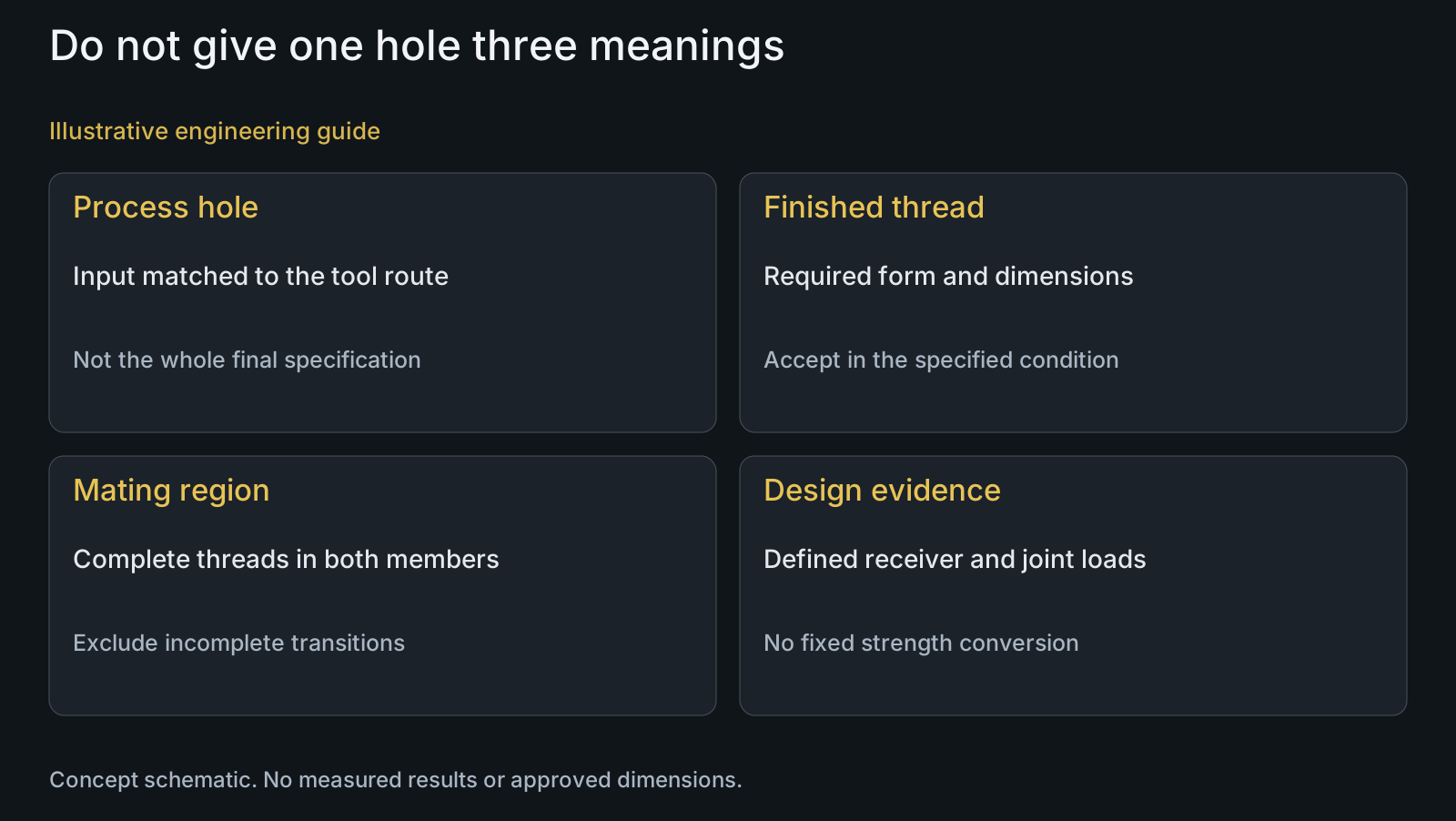
Changing a titanium pivot receiver's pilot-hole diameter does not imply a fixed percentage change in thread strength. The hole must suit the selected threading route and produce the specified finished thread geometry. For an OEM reviewing an internally threaded axle, identify the thread form, size, pitch and class, the exact titanium condition and the complete mating length actually available. Percentage of thread is not the same as axial engagement length. The entrance, tool lead and hole bottom can limit usable threads even when the drilled depth looks sufficient. Assess the finished receiver and mating bolt rather than assigning a strength number to one hole measurement.
Hero: concept illustration of example hardware and its application. It is not a factory photograph, tested component or approved production geometry.
Tie the pilot hole to the selected threading route
Begin with the required finished internal thread, not an isolated drill diameter. Identify its system, size, pitch, handedness and applicable tolerance or acceptance requirements. The process hole is an input to producing that geometry; it is not the complete drawing requirement.
Cut tapping removes material, form tapping displaces it and thread milling cuts through a programmed path. Their pre-hole requirements cannot be assumed identical. If the proposed route changes, revisit the applicable tool and hole relationship rather than retaining a number solely because it worked with another process.
The stainless form-tapping guide explains the process distinction, but does not authorize that route for a titanium grade. Confirm the selected tool's application to the actual material and geometry. A tool's titanium-colored coating is not proof that it is intended to machine titanium.
Percentage of thread is not a strength certificate
Guhring's tap-drill discussion explains that drill selection affects thread geometry and tapping behavior, and that strength is not directly proportional to percentage of thread. Its general examples do not establish a numerical relationship for a particular titanium receiver.
A smaller pilot hole is therefore not automatically the correct improvement. The selected process must still operate suitably and the finished thread must meet its specification. Do not increase material engagement without reviewing the tool application and required geometry.
Equally, enlarging the hole for easier processing is not permission to relax the finished-thread requirements. Assess the proposed change against the actual internal thread and its design basis. Any strength prediction requires its own defined geometry, materials, load and applicable method, not a blanket percentage per diameter change.
| Input or evidence | Useful subject | Risk of confusing it with another requirement | Review or check |
|---|---|---|---|
| Pilot-hole diameter | Input for the selected threading route | Called the complete thread specification | Actual tool, process and finished limits |
| Percentage of thread | Cross-sectional geometry input | Called axial engagement or fixed strength | Applicable geometry and separate design basis |
| Drilled depth | Extent and bottom of the process hole | Called complete-thread depth | Entrance, tool lead and bottom clearance |
| Complete mating length | Full threads actually engaged | Inferred from one member's overall length | Both members in the intended seated position |
| Applicable thread-gauge result | Defined finished-thread check | Called complete assembly or strength approval | Separate receiver, seating and load requirements |
Drilled depth and complete thread depth are different
Distinguish the hole depth, tool travel and length of complete thread. The entrance chamfer, incomplete lead region and bottom shape do not become full-form mating threads just because they appear within the overall drilled length.
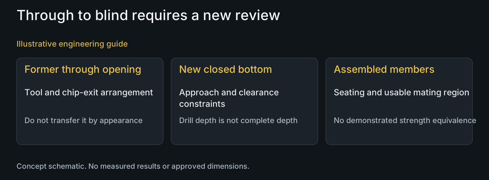
Identify the selected tool's approach and required clearance at the bottom. A through-hole route may provide a chip-exit path that a blind receiver lacks. OSG's titanium through-hole tap description explicitly describes chips pushed forward through the opening; that application is not automatically transferable to a closed bottom.
For the drawing review, mark the complete-thread extent and the allowed bottom geometry separately. Then establish whether the proposed manufacturing route can produce both. No universal drill-depth addition or minimum number of complete threads is assigned here.
Count the threads that can actually mate
Usable engagement depends on both members in the assembled position. A long internally threaded region may not all be reached by the mating bolt; a long bolt may instead bottom out before the intended seating surfaces meet.
Review the external thread runout, internal entrance, complete-thread regions, final seating position and bottom clearance together. The effective-engagement guide develops that joint-level relationship. The pilot-hole review supplies the manufactured internal geometry rather than approving engagement from a drill-depth label.
Retain the receiver's outside geometry as well. A wall near the thread, a shoulder transition or a cross-hole can change the design question independently of pilot diameter. Identical thread designations do not imply that receivers with different surrounding sections have identical strength.
Inspect the process input and final output for different reasons
A pre-thread hole check can confirm a process input within its specified scope. It does not inspect the subsequently generated pitch diameter, complete form or supplied thread condition. Conversely, one applicable thread-gauge check does not measure every receiver feature.
Specify the required finished-thread and dimensional checks, including complete depth where relevant, in the agreed acceptance condition. The metric thread-class guide separates class labels from material strength and thread-system identity.
Where finishing or a pre-applied product follows threading, state whether the earlier evidence still represents the required supplied condition. For a suspect hole change, keep the actual pre-hole and finished-thread observations separate; a drawing of the intended geometry is not an observation of the produced part.
A blind-hole revision changes more than the endpoint
Illustrative engineering example: assume a titanium receiver originally has a through hole. A packaging revision makes it blind while retaining the thread designation and nominal axial space. No actual tap trial, hole measurement or load result is supplied.
The review now checks the tool's chip path, approach and bottom clearance and marks the required complete-thread extent. Keeping the earlier pilot diameter alone cannot establish that the revised receiver supplies the same usable engagement. The mating bolt's seating and bottom clearance also need assessment.
Send both member drawings and STEP, titanium grade and condition, thread specification and complete-depth requirement to CNC turning review. Connect the material basis and supplied finish to the proposal. PremFixer will review the process-hole and final receiver requirements without inventing a strength improvement or claiming every threading route is available for every titanium component.
Questions buyers need to confirm
Does a larger tap hole always reduce strength by a known percentage?
No universal percentage applies. Review the resulting thread geometry, complete mating length, material conditions and receiver section against the design method and load requirements.
Is percentage of thread the same as engagement length?
No. It describes a cross-sectional geometry input, whereas engagement length concerns complete mating threads along the axis. Neither should replace the other's requirement.
Can a cut-tap hole size be retained for form tapping?
Do not assume so. The processes generate the thread differently. Confirm the proposed tool's material application and pre-hole requirements while preserving the specified finished-thread limits.
Does a deep drilled hole guarantee equally deep complete threads?
No. Entrance geometry, the tool's lead and the hole bottom limit the complete region. Mark the required complete-thread depth and provide clearance suitable for the reviewed route.
Does a thread-gauge pass prove the complete pivot joint?
No. It supports its applicable thread check. Remaining wall, seating, effective engagement, bottom clearance and required load validation are separate subjects.
What is needed for a titanium receiver-thread RFQ?
Send both member drawings, exact titanium condition, thread system, size, pitch and class, hole and complete-thread depths, bottom geometry, finish and quantities. Identify the intended assembled position and acceptance scope.
Technical references and scope
Guhring: Tap Drill Calculator and technical discussion. Relevant complete discussion173–177 and calculatorinputs127–151 read. Geometry/process dependence and nonproportional strength principle only; suggested percentages, numerical comparisons and calculator outputs not transferred.
OSG: EXOPRO-Ti through-hole tap description. Relevant description481–499 read. Titanium through-hole application and forward chip path only; specific thread size, coating-life multiplier or company tool ownership not adopted.
Explore related component, material and sourcing decisions in the customer decision knowledge center. For a drawing review, use the Drawing/BOM RFQ path.
Review the pilot hole and finished titanium receiver together
Send the receiver and mating-bolt drawings and STEP, exact titanium grade and condition, thread specification, required complete depth, hole bottom and supplied finish. PremFixer will review the threading input, usable geometry and applicable inspection scope for the proposed component.
Discuss the drawing and BOM