
7075 carbon frame compatibility is a property of the complete interface, not a yes-or-no label for an aluminum pivot bolt. Where aluminum is electrically connected to conductive carbon and an electrolyte is present, galvanic corrosion needs consideration. The actual joint may instead contact a metal insert through coatings, a sleeve and spacers. Identify those layers and the moisture path before selecting protection. Replacing the bolt with titanium does not remove an aluminum insert or validate the revised clamp stack. For an OEM decision, review both corrosion protection and the mechanical function of the finished assembly; do not authorize a material swap from the frame label alone.
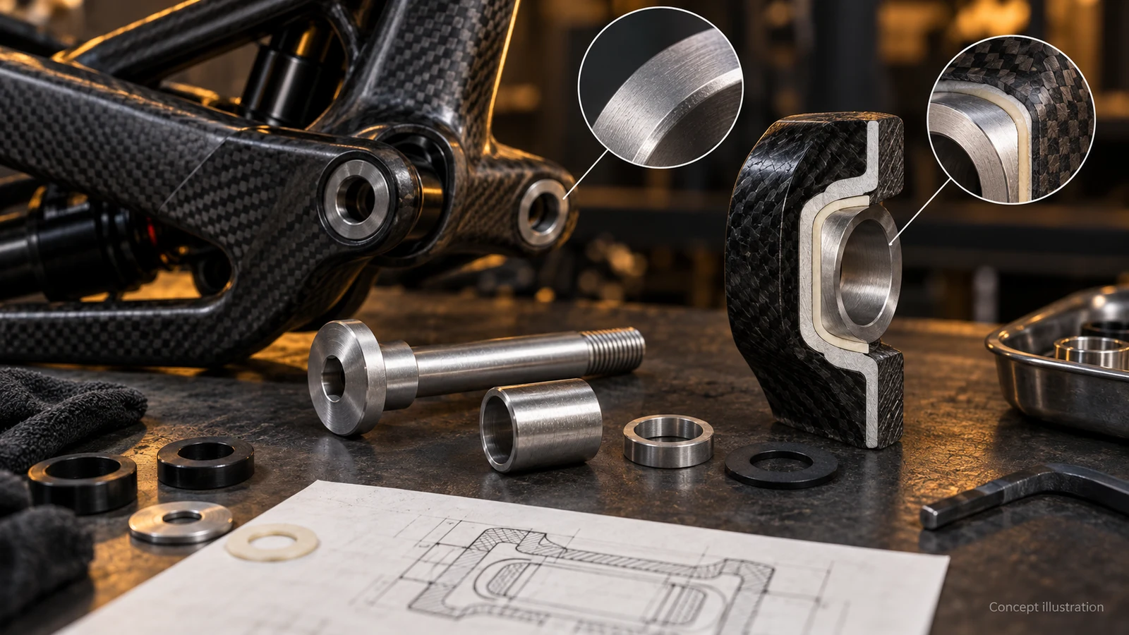
Hero: concept illustration of example hardware and its application. It is not a factory photograph, tested component or approved production geometry.
Locate the aluminum that could be exposed
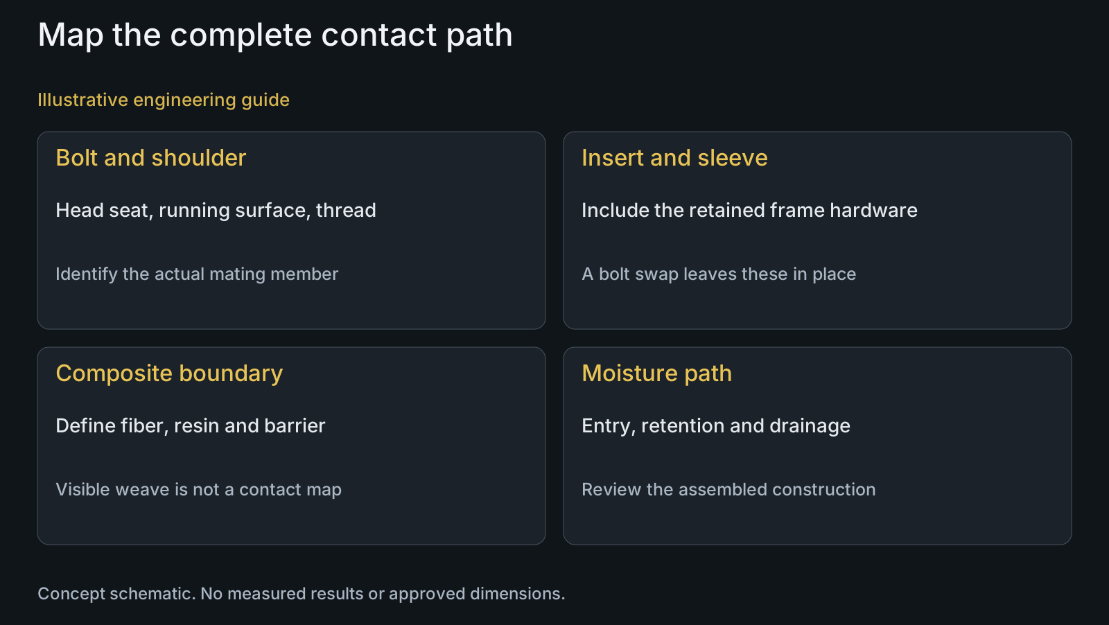
A carbon-frame pivot can contain a bonded metal insert, bearing supports, a sleeve and several washers. Draw a section through the joint and label each contact. Identify what the bolt head seats against, where its shoulder runs and which component receives the thread. Carbon frame is not a sufficient description of any one of those surfaces.
NASA's electrical-bonding handbook describes carbon-fiber composites as commonly cathodic in galvanic couples with metals and identifies aluminum corrosion where the relevant contact and moisture are present. This supports reviewing aluminum at the interface. It is aerospace guidance, not a bicycle compatibility approval, a corrosion rate or a universal voltage-based acceptance rule.
Distinguish exposed conductive fibers from the intended resin, coating or isolation layer. A surface photograph may not reveal the complete electrical connection through other components. Ask the frame designer to identify the controlled interface construction and any permitted exposed areas rather than treating visible weave as proof that every touching part contacts bare carbon.
Separate the barrier from the loaded contact
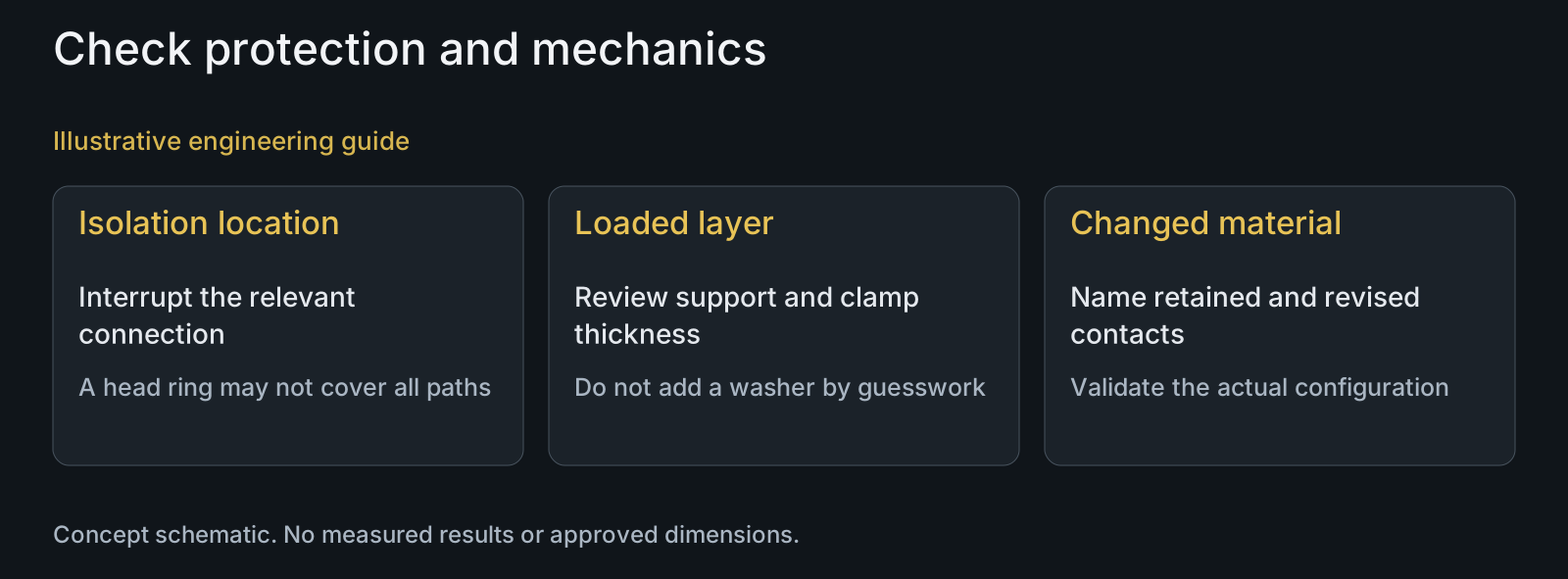
An isolation detail has a location and a mechanical role. A ring beneath the head does not necessarily interrupt a connection through the shoulder, insert or another washer. Trace the proposed interruption across the relevant surfaces. The mixed-material pivot review covers metal couples; a carbon interface additionally needs its laminate and insert construction defined.
FAA composite-structure guidance discusses isolation between some composite and metal interfaces, including carbon and aluminum, alongside fastener-installation damage. The transferable principle is to assess protection and installation together. It does not prescribe a washer material, isolation thickness or installation setting for a bicycle pivot.
For the mechanical review, ask whether the proposed layer lies in a clamped load path or changes a bearing seat. Its thickness, compression behavior and placement become design inputs. Do not add a soft washer to a controlled stack solely because it appears insulating. The responsible designer must establish that the revised contacts still perform their support and clamping functions.
| Proposed configuration | Possible decision benefit | Remaining concern | Required review |
|---|---|---|---|
| 7075 bolt with defined protection | Retains the selected hardware material | Actual continuity at threads, seats and shoulder | Map finished and masked contacts in the assembly |
| Isolation ring beneath the head | Interrupts the intended head contact if effective | Other conductive paths and changed clamp thickness | Trace the full path and assess the loaded layer |
| Titanium replacement bolt | Changes the replaceable fastener material | Aluminum insert and frame boundary remain | Review retained parts plus revised geometry and installation |
| Revised insert or laminate boundary | Targets the frame-side interface itself | Changes frame construction and responsibility | Frame-authority assessment with representative validation |
| Added sealing or drainage detail | Addresses a defined moisture path | Access, durability and interference with joint function | Evaluate the assembled construction and service conditions |
Define protection after machining and assembly
For a proposed anodized aluminum part, identify the protected faces and any intentionally masked regions. Thread contact, head seating and installation can differ from the appearance surface. A drawing that only says anodized does not show whether the relevant carbon-to-metal connection is interrupted in the assembled condition.
Review surface treatment with the final fit definition. A protection change can require different finished dimensions or contact allowances. The hard-anodized pivot guide explains the separate finish-and-fit decision; color matching is not evidence of isolation at an inaccessible interface.
Identify where water can enter, remain and leave around the insert and sleeve. Sealing and drainage proposals must fit the actual frame construction and service access. Do not prescribe an unspecified grease or assembly paste as a universal corrosion barrier. Its suitability and effect on the assembly procedure need approval for the particular joint.
Compare a bolt change with an interface change
Changing the bolt is a bounded proposal: name which contacts and functions change and which remain. If a metal insert is retained in the frame, its material and connection to the laminate stay in the review. A corrosion-resistant replacement bolt cannot be taken as evidence that another member is protected.
The replacement also needs the correct shoulder, grip, thread and seating geometry. Do not carry an installation setting from one surface configuration to another without review. The decision may be a revised aluminum protection detail, a different replaceable component, or a frame-interface redesign; it is not automatically a titanium purchase.
Define how the chosen configuration will be assessed in its assembled condition. Include the relevant contact, moisture exposure, permitted surface damage and functional checks after that exposure. Keep the evidence tied to the parts and construction actually reviewed. A bare bolt comparison cannot demonstrate behavior at a bonded frame insert.
Illustrative review: the insert remains after the bolt changes
Illustrative engineering example: assume a carbon-frame linkage uses a 7075 shoulder bolt and a retained aluminum insert. A purchasing proposal replaces only the bolt with titanium and adds an insulating ring beneath its head. No actual corrosion, service duration or proven protection result is assumed.
The section review shows that the proposal changes the head contact but does not address the retained insert-to-frame boundary. It also leaves the sleeve support and finished grip to be checked. The team therefore separates the replaceable-bolt drawing from the frame designer's interface definition rather than calling the entire assembly compatible.
The useful outcome is a better comparison: one option preserves the bolt and revises the defined protection system; another changes the bolt while retaining a separately assessed insert interface. Neither option is approved by this example. PremFixer can manufacture drawing-defined hardware and coordinate specified finishing inputs; the customer's assembly validation establishes which configuration is suitable.
Questions buyers need to confirm
Is 7075 automatically unsuitable for every carbon-frame pivot?
No blanket conclusion follows from the frame and alloy names. Identify the actual insert, sleeve, laminate boundary and finish. The selected configuration needs its own corrosion and mechanical assessment; this article does not approve direct bare contact.
Is the concern only that aluminum will damage the carbon fibers?
No. Aluminum can be the vulnerable member in the relevant galvanic interface. Determine where that metal is located and electrically connected. Do not describe an unspecified frame failure or corrosion rate as if it were observed.
Will one insulating washer isolate the whole pivot?
Only if the defined arrangement interrupts the relevant connection, which cannot be assumed from its presence beneath the head. Check the shoulder, thread, insert and other contacts. Its location and effect on the loaded stack also need design review.
Does an anodized surface prove the assembled interface is protected?
Not by its appearance alone. Identify protected and masked zones, finished dimensions and installation contacts. The drawing and representative assembled assessment need to address the actual protection path rather than just the external color.
Does a titanium replacement remove the aluminum insert concern?
No. It changes the bolt, not an aluminum insert that remains in the frame. Compare the retained interface separately and review the replacement's geometry, contact condition and approved installation procedure.
What inputs make a carbon-frame compatibility RFQ useful?
Provide the joint section, bolt and insert drawings, sleeve and washer BOM, alloy conditions and protection zones. Identify expected wetting, cleaning and service access. These inputs distinguish a hardware manufacturing quote from a frame-interface redesign or assembly qualification.
Technical references and scope
NASA MSFC-HDBK-3697, Electrical Bonding Design Guide, section 5.3.6.1. 2014 aerospace handbook used for the general carbon/aluminum galvanic mechanism only; numerical potentials, program thresholds, plating prescriptions and bicycle approval not adopted.
FAA AC 20-107B with change 1, Composite Aircraft Structure, paragraph 6.e. Composite/metal isolation and fastener-installation damage considered together; aircraft guidance is not a bicycle installation rule or design qualification.
Explore related component, material and sourcing decisions in the customer decision knowledge center. For a drawing review, use the Drawing/BOM RFQ path.
Review the complete carbon-to-metal interface
Send the controlled frame-interface section, hardware drawings or STEP models, mating BOM and protection requirements. Identify which parts may change and which remain in the frame. PremFixer will review the drawing-based hardware and finishing scope, while frame construction and application-specific validation remain with the responsible customer team.
Discuss the drawing and BOM