
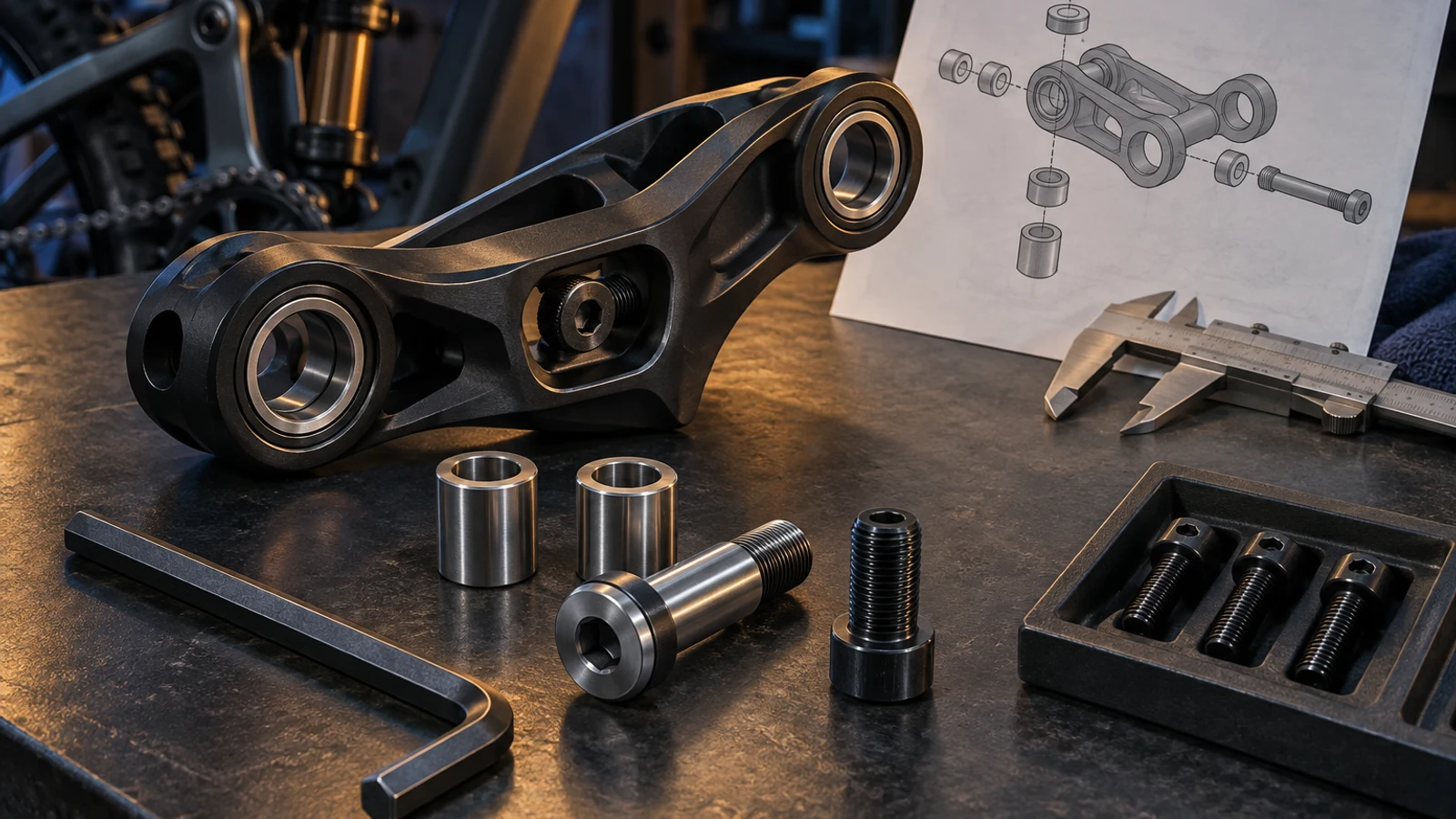
An ISO 4762 socket-head screw can be a useful pivot clamp member when its actual geometry fits the head recess, tool path, contact stack and threaded receiver. It is not automatically a bicycle-specific pivot axle. If the screw must also locate a bearing or set a functional spacing relationship, define that feature rather than infer it from the head style. Nor does an internal socket guarantee the smallest installation envelope: the head and the tool each need space. Start by identifying the function the screw must perform. PremFixer can then discuss a defined custom feature where standard geometry leaves an actual interface requirement unmet.
Hero: concept illustration of example hardware and its application. It is not a factory photograph, tested component or approved production geometry.
Use the product reference for the product it describes
ISO 4762:2004's public scope concerns coarse-pitch hexagon socket head cap screws of product grade A. It does not describe a particular bicycle's bearing stack, service direction or model-specific pivot fit.
Treat a selected product geometry as a candidate. Compare the required head, shank and thread against its actual definition, including separate material and finish requirements. A drawing that borrows a head style while changing its shoulder or drive should say what is custom instead of imply unrestricted conformity.
No comparative evidence supports calling this style universally the largest bearing area or smallest recess solution. The useful question is whether its defined features satisfy this joint better than the alternatives under the same conditions.
Check the head envelope and the tool path separately
The head needs radial and axial clearance. The tool needs an insertion direction, usable engagement and room for the intended operation. A head can fit inside a recess while a neighboring link prevents the tool from reaching its socket properly.
Include both installation and later removal in the review. A tool path available before another component is installed may disappear on the assembled bicycle. State any required disassembly rather than present an inaccessible head as routinely serviceable.
Use an assembly model or relevant physical mock-up to examine the intended tool, not an abstract line through the drive. The drive and tool-access guide addresses access in more detail. A smaller or different drive is a proposed design change, not a remedy to apply without assessing the new interface.
| Interface question | Standard candidate can work when | Custom review is triggered by | Verification |
|---|---|---|---|
| Head packaging | Defined envelope clears the recess | Head height or diameter conflicts | Compare actual head and recess limits |
| Tool operation | Intended tool enters and operates | Link or cover blocks usable access | Check assembled service path |
| Head contact | Intended face receives the clamp action | Special contact or transition needed | Inspect defined contact surfaces |
| Locating function | Separate qualified support performs it | Screw must provide a defined seat | Identify the working surface and fit |
| Receiver reach | Useful threads match the stack | Length or thread distribution conflicts | Check seating, depth and engagement |
| Supplied condition | Material and finish requirements align | Custom finished condition required | Reconcile the actual specification |
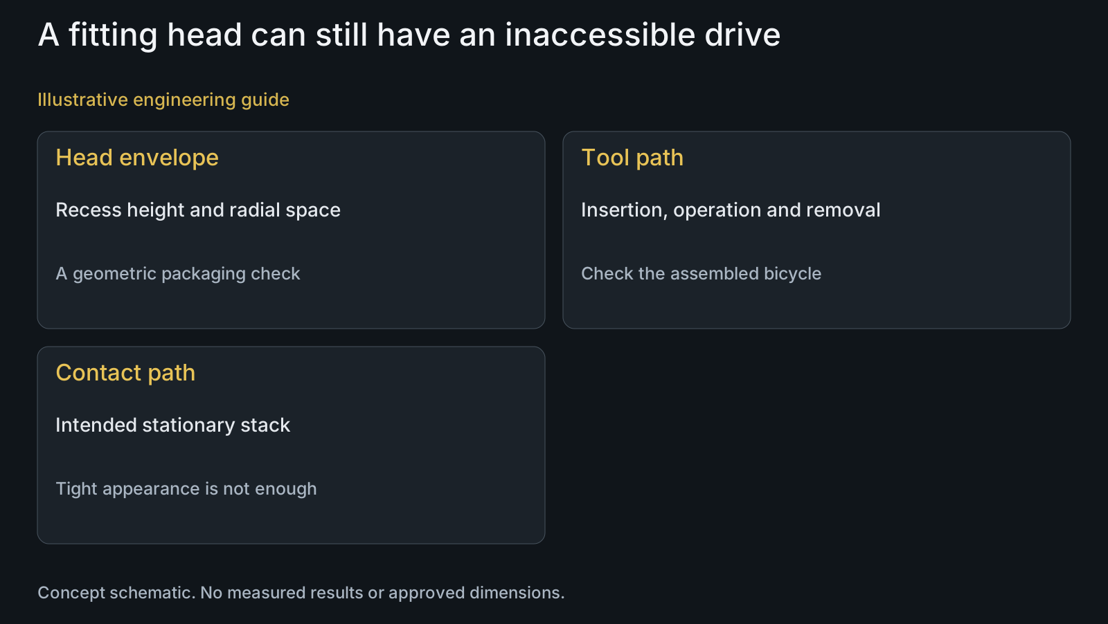
Identify what is contacted when the screw tightens
Map the contact from the head through the intended stationary stack to the receiver. In a recessed joint, include the face below the head and any washer or sleeve. Visible head seating does not establish that the intended inner-ring or spacer faces are engaged.
Check clearance around the head transition and adjacent moving parts. An unintended contact can make the assembly appear tight while imposing a different constraint. Inspect the selected bearing and sleeve requirements for their actual contact arrangement rather than assign a universal shoulder or relief value.
The distinction matters for quotation: head diameter alone is not enough to price a functional custom interface. Provide the receiving face and relevant neighboring geometry, or state explicitly that those fields remain open.
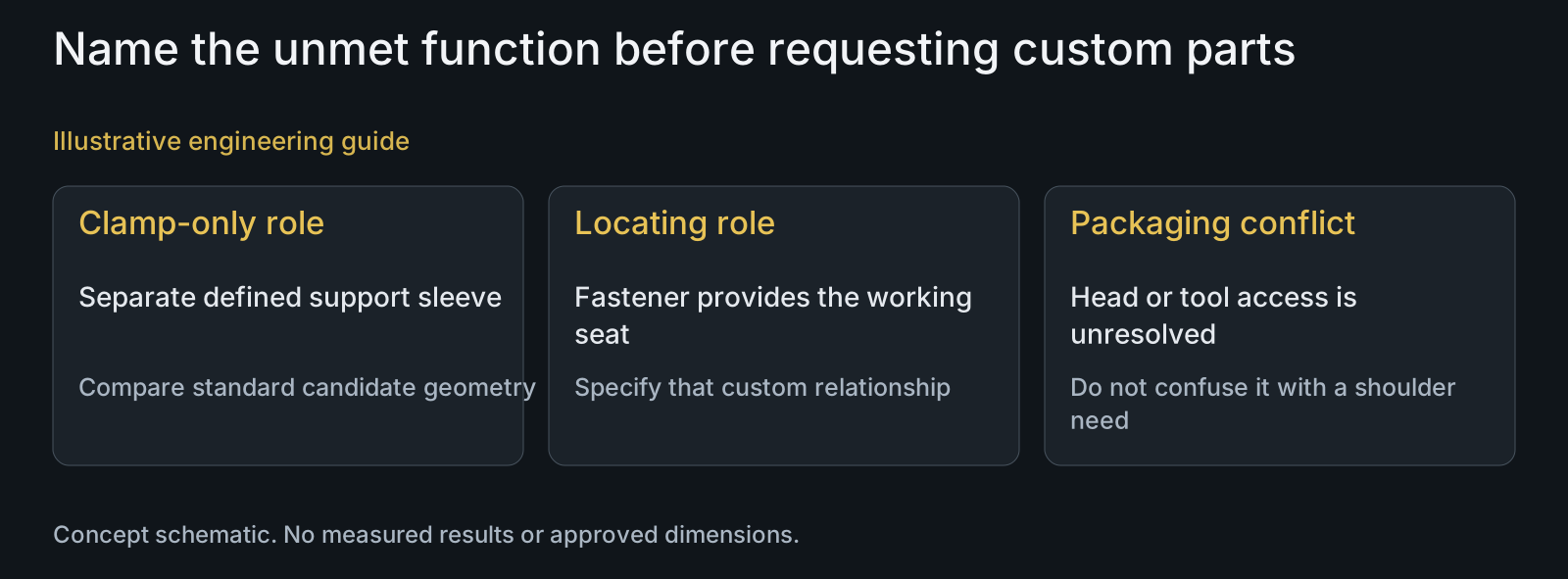
Decide whether the screw clamps or also locates
Where a separate qualified sleeve provides the required support surface, the screw may primarily clamp the defined stack. Where the screw itself must locate a bearing or mate with a bushing, its working section needs a specific definition. Similar socket heads can therefore belong to different interface concepts.
The shoulder-versus-threaded interface guide explains those architectures. This article uses that distinction to identify a custom-design trigger: a required function that the proposed standard product does not actually provide.
Do not add a shoulder just because the assembly is called a pivot. Equally, do not omit a required locating feature because a standard screw is easier to purchase. Define the responsible component, then select its features. Keep the full-suspension application context specific to the local joint.
Match useful thread reach to the receiver and stack
Compare the head seating position, clamp-stack extent, useful thread region and receiver depth. A screw that bottoms in a blind receiver can resist further turning before the intended faces are clamped. Apparent tightness is not a substitute for verifying the contact relationship.
At the other extreme, insufficient useful reach may leave the intended engagement unavailable. The required engagement cannot be assigned from the head style alone; it depends on the actual receiver, geometry, materials and applicable design basis.
If standard length or thread distribution cannot serve the defined stack, specify the needed custom relationship. The CNC-turning overview and materials hub support that manufacturing discussion without promising a particular fit, processing route or universal size range.
Compare two candidates for a recessed clamp joint
Illustrative engineering example: assume a pivot uses a separately defined support sleeve and a socket-head clamp screw. One candidate's head fits the recess, but the chosen tool cannot enter along the required direction with the neighboring link installed. No actual model, dimensions or test outcome is assumed.
The team separates a packaging issue from a locating issue. It reviews the recess and service path rather than immediately add a custom shoulder. It also checks receiver depth and the clamp stack, since changing the selected screw length to gain access would not necessarily solve either contact or tool clearance.
Possible responses include revising access, specifying an acceptable service sequence or assessing a different defined head/drive. Each affects different features. Provide the drawing and BOM RFQ pack so a custom request names the unmet function and its mating conditions instead of asks for a generic 'better pivot screw.'
Questions buyers need to confirm
Is ISO 4762 a bicycle pivot compatibility standard?
No. Its product scope does not define your frame's local joint. Compare the selected screw with the actual head, contact, receiver and locating requirements.
Does an internal socket always need the least space?
No universal comparison is established. Check head height and diameter separately from the intended tool's insertion and operating path. An enclosed recess can fit the head while blocking service access.
Does every socket-head pivot screw need a precision shoulder?
No. Identify which component provides the working support surface. A separate qualified sleeve may serve that role; if the screw itself must locate, specify the relevant feature rather than infer it from the head.
Why can a screw feel tight without clamping the intended stack?
One possible cause is bottoming in a receiver before the intended faces contact. Compare receiver depth, usable reach and the stack; do not infer clamp condition from resistance to turning alone.
Can a low head solve a tool-access problem automatically?
No. It is a changed geometry to evaluate, including the drive and relevant head requirements. Check the real tool path and affected contact rather than assume a shorter head resolves every obstruction.
What makes a custom request useful to the manufacturer?
Name the unmet function and provide its mating geometry: recess and tool path, support seat, contact stack or receiver reach. Include material, finish and drawing/BOM definitions so the offer addresses a specific interface problem.
Technical references and scope
ISO 4762:2004 public scope. Socket-head coarse-pitch screw product scope only; no bicycle-specific interface, dimensional comparison or universal packaging superiority inferred.
Explore related component, material and sourcing decisions in the customer decision knowledge center. For a drawing review, use the Drawing/BOM RFQ path.
Show the interface that standard geometry does not satisfy
Send the screw drawing or candidate reference, assembly STEP, relevant sleeve and receiver details, BOM, material and finish requirements. Include the intended tool and service direction so PremFixer can discuss the specific custom feature and manufacturing scope.
Discuss the drawing and BOM