

CONCEPT — Generic pivot interface; not a released frame or product drawing. Applicability: use the actual model, pivot stack, load path, fit, clamp strategy and validation plan.
A pivot fastener can look fully engaged and still place the wrong surface under the bearing stack. That is why “shoulder bolt or fully threaded bolt?” is not the first engineering question.
The first question is: what component provides the working surface?
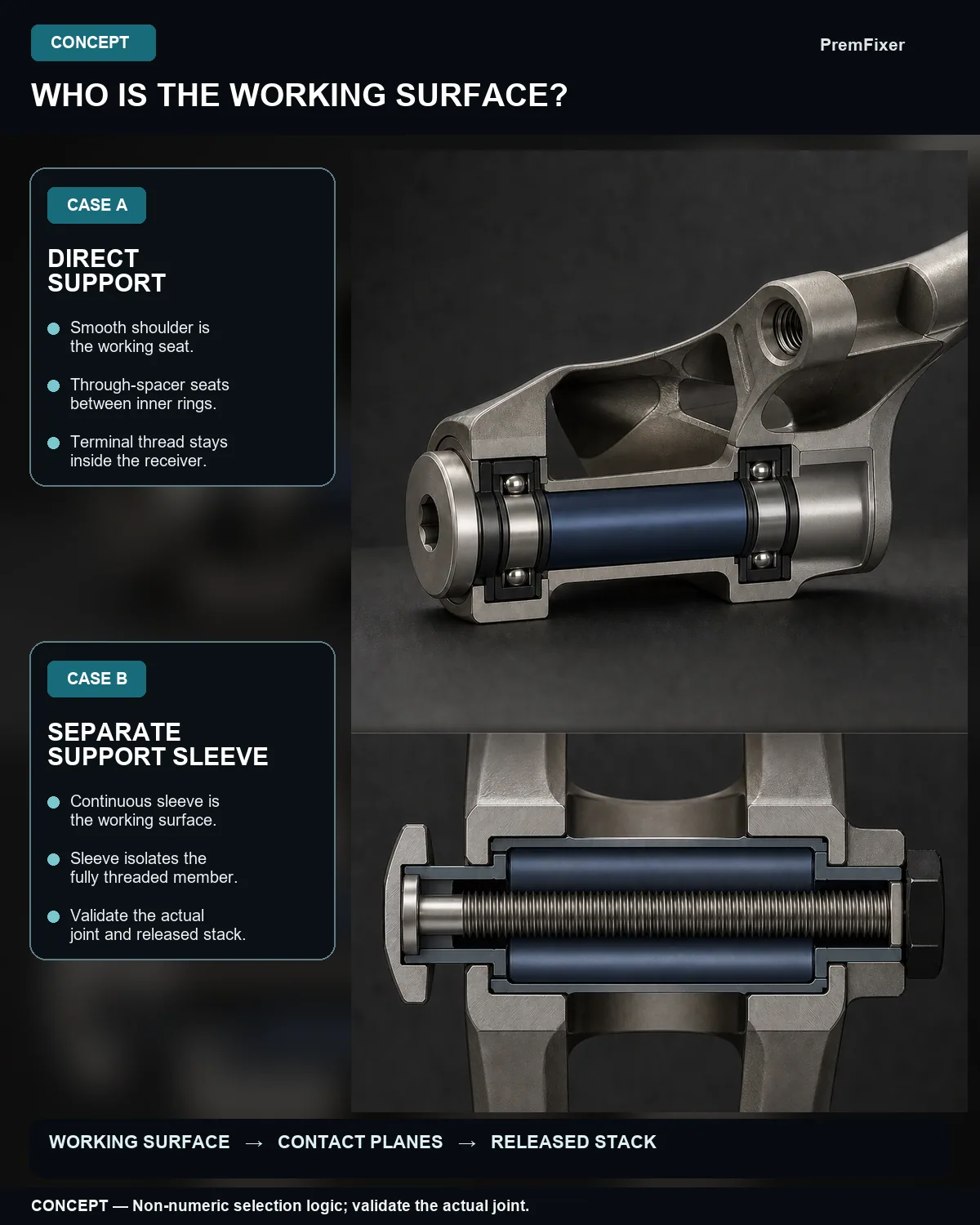
Sometimes the bolt or axle directly supports bearing inner rings, locates sleeves or acts as a bushing journal. In that case, its smooth section is part of the interface. In another valid architecture, a separate sleeve, axle, collet or dedicated inner ring provides the complete support surface while a fully threaded member supplies clamp load.
The purchase name alone does not distinguish those cases. The released stack does.
Start with four different roles
A useful review keeps four roles separate even when one component performs more than one of them.
Working seat or journal. This is the cylindrical surface that supports a bearing inner ring or mates with a plain bushing. Its fit, form, surface condition and motion requirements belong to the selected bearing or bushing system.
Clamp member. This component develops preload through the head, seat and threaded receiver. In a preloaded joint, friction may transfer service shear before slip; that does not remove the need to review what happens at the direct support and potential shear planes.
Spacer or sleeve. A center spacer can support opposed inner-ring faces and complete the clamp path. A separate through-sleeve or dedicated inner ring can also isolate a threaded fastener from the working interface. A floating ring with gaps to the intended inner-ring faces is not a defined support path.
Threaded receiver. A nut, insert or tapped member provides engagement and closes the clamp path. Thread runout and engagement should not drift into an intended seat/contact span unless the actual design explicitly verifies that condition.
Once these roles are mapped, the hardware label becomes a consequence rather than a starting assumption.
What a smooth shoulder changes
NASA’s threaded-fastener method distinguishes between a shear plane crossing the full-diameter body and one crossing the thread’s minimum section. That is aerospace guidance, not an MTB test result, but the geometry boundary is useful: if the fastener itself crosses an intended shear plane, keeping that plane on the smooth full-diameter section avoids assigning it to the thread root section.
A precision shoulder can also serve as an alignment, spacing or bearing surface. The word “shoulder,” however, does not prove that its diameter, length, fit, form, finish, hardness or material is correct for the joint. Those remain drawing and validation inputs.
The defensible statement is therefore narrow:
A smooth shoulder is valuable when it is the qualified working seat or full-diameter section across the intended support/contact or potential shear span.
It is not a universal claim that a shoulder bolt is stronger, safer or longer-lived in every pivot.
Why direct thread support needs justification
A conventional rolling-bearing inner ring expects a defined seat and fit. SKF’s guidance links incorrect fit, relative movement and form/support problems with risks such as creep, wear, vibration and fretting. That does not mean every thread under every inner ring will fail. It means a generic external thread is not, by itself, evidence of a qualified cylindrical seat.
Plain bushings add another boundary. GGB’s handbook makes mating-surface material, finish and operating conditions part of the wear system. If the bushing runs directly on the pin, thread flanks are not a default journal. The selected bushing supplier’s requirements and the actual pressure, motion, lubrication, contamination and surface state still control.
This is why direct thread contact should be treated as an application-specific condition to justify—not as a visual shortcut and not as an automatic failure label.
The legitimate fully threaded exception
Fully threaded does not automatically mean wrong.
igus documents a multi-component bearing architecture in which a dedicated inner ring supplies the sliding surface and isolates the bearing from the shaft’s thread or roughness. The product-specific example is useful because it makes the functional separation explicit: the inner ring is the working surface; the shaft or fastener is not.
The same engineering pattern can support a fully threaded clamp member when all of the following are true for the actual joint:
- one qualified sleeve, axle, collet or inner ring provides the complete working surface;
- the external thread does not directly support the ordinary bearing inner ring or bushing;
- the clamp path, receiver engagement and locking method are defined;
- any thread crossing a load plane is included in section and combined-load verification;
- assembly and service evidence match the released stack.
That is an exception architecture with its own requirements. It is not permission to place an ordinary cartridge-bearing inner ring or plain bushing directly on thread crests.
Shoulder length follows the released stack
“Make the shoulder equal to the stack width” is not a safe universal formula.
The released support span may include frame or link tabs, bearing inner rings, bushing sleeves, a center spacer, washers or collets, under-head geometry, relief/runout and the receiver-side transition. The smooth section should cover every intended seat/contact or potential shear zone. At the same time, the selected geometry must still let the intended stack clamp correctly and preserve the required receiver engagement.
That makes shoulder length a tolerance-stack and clamp-strategy decision. Exact dimensions cannot be inferred from a suspension family, a product photograph or a generic section view.
Loads and wear are conditions, not slogans
“The shoulder carries shear” compresses several mechanisms into one phrase.
An actual fastener may see tension from preload, direct shear after slip, bearing/contact load and bending from clearance, gaps or eccentricity. The inner rings, spacer, tabs and receiver redistribute those loads. Surface condition, fit and micromotion influence wear and fretting. A smooth section can clarify the intended support geometry, but it does not eliminate bending, play, fretting or fatigue by itself.
A release review should therefore ask:
- What transfers load before slip, and what transfers it after slip?
- Which component carries bearing or bushing contact?
- Where are potential shear planes relative to shoulder, runout and thread?
- Can gaps or non-supporting spacers introduce bending?
- Does the clamp strategy create the intended inner-ring/spacer compression without binding the moving interface?
- What service, environment and validation evidence supports the conclusion?
If those inputs are open, the engineering conclusion should remain open too.
Architecture names tell you where to inspect
VPP/dual-link, Horst/four-bar and single/flex labels are useful topology maps. They are not fastener specifications.
VPP or dual-link. Several upper- and lower-link pivots may use different bearing pairs, spacers, collets, receivers and service directions. Each local interface needs its own review.
Horst or four-bar. Main, rocker, rear and shock-related joints can have different physical roles and different axle, sleeve or clamp arrangements. One architecture label does not make them interchangeable.
Single pivot. Fewer physical pivots do not reduce the need to define the remaining main interface. Its stack and service path still control the hardware.
Flex pivot or flex stay. Some apparent pivot functions are flexures with no bolt at that location. The remaining physical joints still require the same seat, clamp, receiver and validation review.
The practical conclusion is simple: architecture narrows the inspection map; the local joint selects the hardware.
A release-ready drawing or RFQ pack
Before selecting or quoting pivot hardware, align the engineering, quality and sourcing teams on the same interface evidence:
- frame model, size, revision and exact pivot location;
- exploded stack and assembly/service direction;
- bearing or bushing type and the component that actually rotates or slides;
- inner-ring, sleeve, spacer, washer/collet, head/seat and receiver details;
- smooth support diameter/length, relief/runout and thread engagement;
- fits, clearances, materials, finishes, hardness, lubrication, sealing and environment;
- clamp/preload target, tightening method, locking strategy and service procedure;
- load cases, load sharing, slip criterion, gaps/eccentricity and fatigue review;
- part- and assembly-level validation required for any strength, play, wear, fretting or life claim.
This pack does not force one bolt family. It makes the reason for the selection reviewable.
Conclusion
A shoulder bolt is not automatically the better pivot bolt. A fully threaded bolt is not automatically the wrong one.
The decision becomes defensible when the drawing identifies the working surface, maps every support/contact and potential shear plane, places thread and runout deliberately, closes the clamp path through a real receiver and preserves a model-specific validation boundary.
Choose the interface architecture first. Then specify the fastener that fits it.
Author & Contact
PremFixer supports engineering discussions around precision bicycle hardware from drawings, samples and BOM/interface requirements. Product selection and release remain application-specific.
Canonical website: https://premfixercnc.com/
References
- NASA. Requirements for Threaded Fastening Systems in Spaceflight Hardware — NASA-STD-5020B. Aerospace scope; public document dated 2021-08-06.
- SKF. Bearing damage and failure analysis.
- GGB. FRC Fiber Reinforced Composite Bearings Handbook.
- Carr Lane. Shoulder Screws.
- igus. iglide PEP multi-component bearing.
- Santa Cruz Bicycles. Suspension.
- Santa Cruz Bicycles. Nomad 4 product support.
- Specialized. FSR Suspension Technology.
- SCOTT. Spark 900 EVO.
- PremFixer. Canonical website. Contact context only.
All web sources were verified by Research on 2026-08-25.
Claim-to-Source Map
| Claim ID | Article claim | Classification | Evidence | Wording boundary |
|---|---|---|---|---|
| C01 | Keeping an intended fastener shear plane on the smooth full-diameter body avoids assigning that plane to the thread’s minimum section. | SOURCE FACT + SCOPE QUALIFIER | S1 | Aerospace method only; no MTB strength gain or safety result. |
| C02 | A real fastener review may need combined tension, shear and bending, including effects from clearance, gaps or eccentricity. | SOURCE FACT + SCOPE QUALIFIER | S1 | No claim that preload eliminates slip or bending. |
| C03 | A rolling-bearing inner ring needs a defined seat and fit; a generic thread does not prove those requirements. | SOURCE FACT | S2 | No universal fit, tolerance or failure claim. |
| C04 | If uneven support or micromotion exists, creep, wear or fretting is a credible conditional risk. | SOURCE FACT + BOUNDED INFERENCE | S2 | Do not state that fully threaded pivots always fret. |
| C05 | A bushing’s mating surface and operating conditions influence wear; thread flanks are not a default journal. | SOURCE FACT + BOUNDED INFERENCE | S3 | No universal finish or MTB life claim. |
| C06 | A precision shoulder can provide an alignment, spacing or bearing surface when its actual specification is qualified. | SOURCE FACT | S4 | No claim that any shoulder screw suits an MTB pivot. |
| C07 | A fully threaded clamp fastener can be valid when a dedicated sleeve or inner ring isolates it from the working surface. | SOURCE FACT / EXPLICIT EXCEPTION | S5 | The igus PEP example does not transfer to ordinary bearings or bushings. |
| C08 | Smooth support length follows the released support stack while preserving clamp function and receiver engagement. | TRANSPARENT ENGINEERING INFERENCE | S1–S4 | No universal shoulder-length formula or allowance. |
| C09 | VPP uses multiple local link interfaces that must be reviewed separately and against model-specific support information. | SOURCE FACT + SELECTION BOUNDARY | S6–S7 | No universal VPP bolt or Nomad-to-all-model inference. |
| C10 | A four-bar/Horst layout contains multiple joints that can use different interface concepts. | SOURCE FACT + SELECTION BOUNDARY | S8 | No architecture-wide hardware prescription. |
| C11 | Single/flex systems may replace some pivot functions with flexures while retaining other physical joints. | SOURCE FACT + SELECTION BOUNDARY | S6, S9 | Do not state that flex-pivot bikes have no hardware. |
| C12 | PS-D04 and PS-D06 may guide only a long-smooth-section/short-terminal-thread silhouette. | PRODUCT-LOCAL OBSERVATION | L1 | No dimension, marking, material, process, torque, compatibility or performance claim. |
Suggested Hashtags
#MTBEngineering #MechanicalDesign #PivotHardware #BearingDesign #FastenerEngineering #SupplierQuality #DesignForAssembly
Start With the Actual Interface
Send the drawing or sample and the application context so the discussion stays tied to the approved part and its joint.
Send a Drawing or Sample