
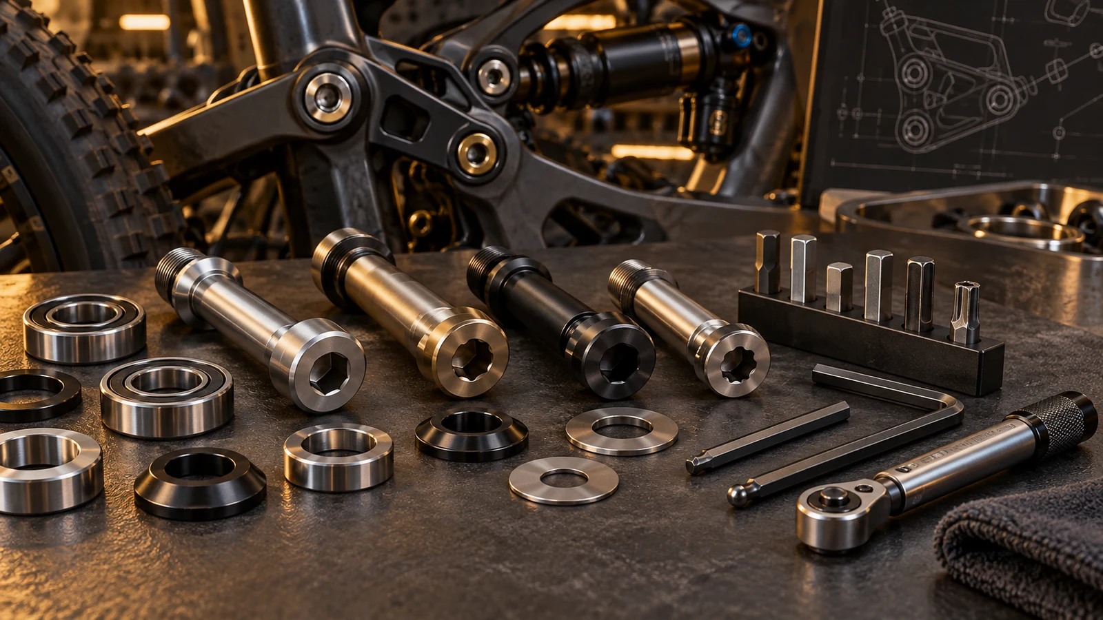
Choose a pivot tool from the actual drive specification and service instruction, not the bolt's thread diameter or a similar-looking socket. Hex, hexalobular and other star-like profiles are not one generic interface. The tool must have the appropriate tip, engagement and access for the permitted operation. A ball end can provide angled access in some applications, but that does not automatically make it suitable for a pivot's final tightening or difficult removal. For an OEM drawing review, examine the assembled tool path and any counterholding requirement. Stop when the drive is damaged or the approved method is unavailable rather than add leverage to an uncertain fit.
Hero: concept illustration of example hardware and its application. It is not a factory photograph, tested component or approved production geometry.
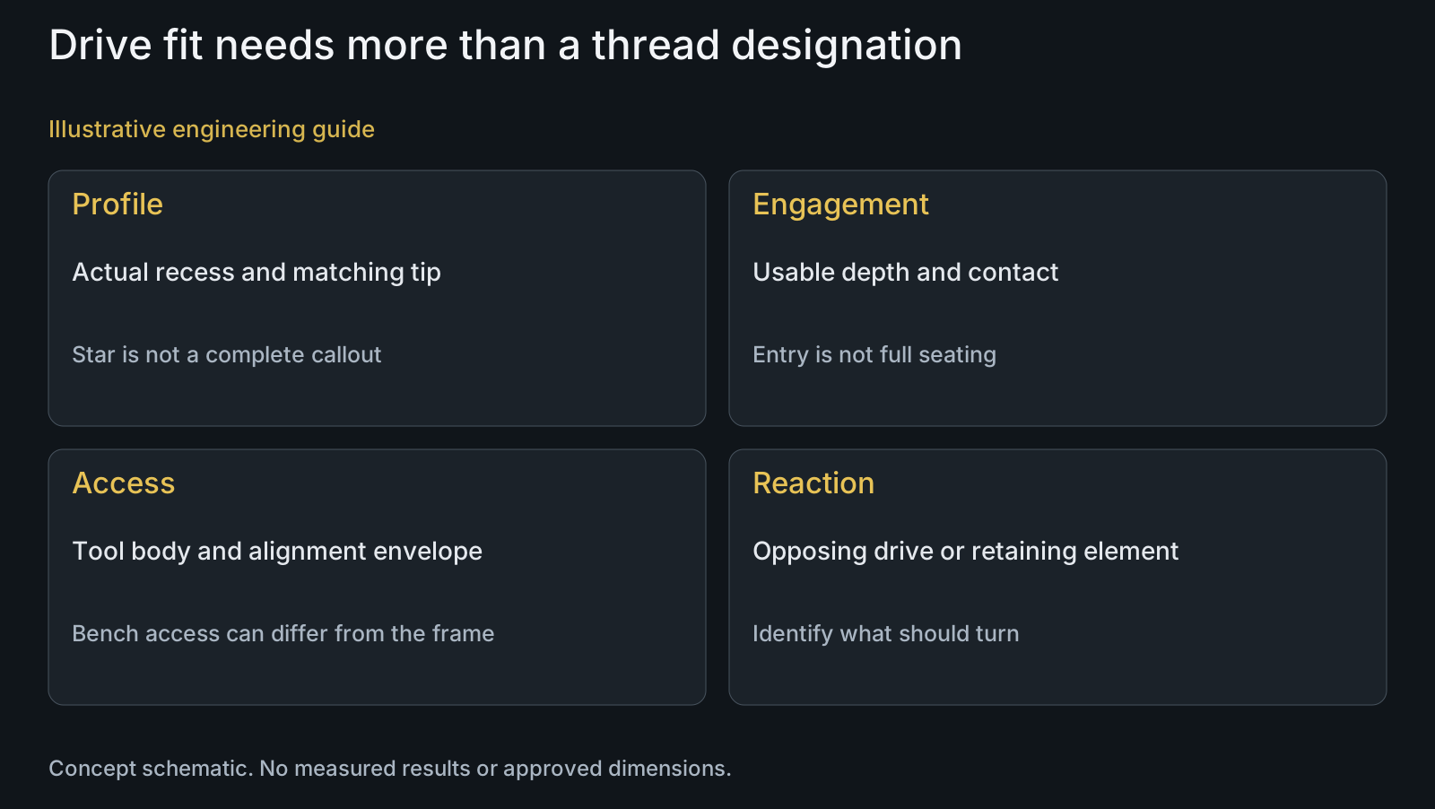
Identify the recess profile separately from the thread
Thread designation does not specify the head's tool interface. Record drive profile, nominal size, usable depth and any special feature from the hardware drawing or service information. A shoulder axle can also contain a different drive or retaining element on its opposite end.
Do not treat star as a complete callout. Wera's TORX PLUS description identifies an elliptical flank form that differs from the ordinary TORX profile. This named profile distinction supports selecting the actual interface, not improvising a cross-profile substitute for a structural pivot.
For an unidentified used part, appearance is a starting observation. Obtain the applicable hardware identity before operating it. The sample reverse-engineering guide addresses drawing definition from samples; copying a worn recess does not establish its original intended profile.
Check engagement before judging tool quality
A premium tool with the wrong profile or size remains the wrong interface. Worn tips, rounded recess surfaces or material obstructing the usable depth can reduce engagement. Establish permitted cleaning and observation before applying force; do not hammer a convenient alternative into the recess.
Distinguish partial entry from full intended engagement. A bit shank can contact the surrounding counterbore before its tip reaches the required position, or a frame feature can prevent alignment. Turning resistance in that situation does not demonstrate that the drive is properly seated.
For a new custom design, review drive depth together with head section, counterbore and tool clearance. Increasing recess depth is not a free manufacturing change because the remaining geometry also changes. Discuss the actual feature and access through CNC turning, rather than promise a universally stronger socket.
| Candidate or condition | Useful role | Risk if assumed sufficient | Confirmation needed |
|---|---|---|---|
| Aligned straight hex tip | Specified hex engagement | Wrong size or partial depth still unsuitable | Profile, size, usable depth and access |
| Ball-end hex tip | Angled access within permitted use | Reach called final-torque approval | Component/tool limits for actual operation |
| Star-like bit | Candidate only after profile identity | Different flank forms called equivalent | Exact drive and nominal size |
| Opposing-side tool | Required reaction or retainer operation | Wrong element turned or held | Assembly method and both tool envelopes |
| Torque wrench with adaptor | Defined controlled input setup | Capacity or convenience becomes joint setting | Tool instructions, orientation and approved method |
| Damaged drive or stuck joint | Escalation condition | More leverage loses interface and evidence | Responsible component-specific service route |
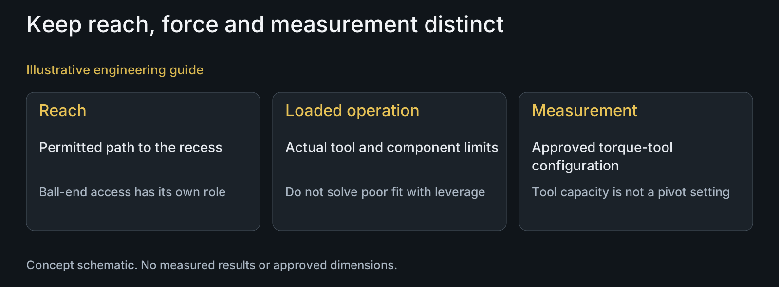
Separate ball-end reach from the loaded operation
Park Tool's PH-2 description distinguishes its ball-end tip for difficult access from its straight tip for high-torque applications. This illustrates different intended tool roles. The named product's description does not establish the correct size or capacity for a particular pivot.
An angled approach changes the contact arrangement from an aligned straight tip. Follow the component and tool manufacturers' permitted use for the operation instead of imposing either a universal ball-end ban or universal permission. Access convenience alone does not approve a final tightening method.
If only an angled tool can reach a critical drive in the assembled frame, treat that as a service-planning issue. Resolve the required access or permitted disassembly under the applicable instruction. Do not infer that the necessary final setting can be applied accurately because the fastener can be spun with a ball end.
Identify reaction and retaining arrangements
A visible drive may belong to an axle, an opposing screw or a separate locking element. Establish what must turn and what must remain held. Operating an exposed recess without identifying the arrangement can leave a retainer engaged or rotate an unintended component.
Include access to both sides when the applicable method requires counterholding. Check whether tool bodies, not just their tips, can occupy the necessary space. Frame members, hoses and shields belong in the assembled access view rather than disappear from a convenient bench illustration.
The assembly-sequence guide discusses operation dependencies. The seized-thread article separates removal planning from receiver acceptance. An appropriate tool does not itself authorize extraction, heat or repair of an uncertain joint.
Keep torque measurement valid for the actual tool setup
Park Tool's torque-wrench guidance calls for full, square bit engagement and warns against using its click-type wrenches as ordinary removal ratchets. Use the instructions for the actual tool, including its supported operation and range, rather than treat every ratcheting torque instrument as a breaker bar.
An adaptor or extension must be considered in the actual measurement arrangement. Its geometry, orientation and tool instructions determine whether the approved method is preserved. This article does not offer a universal correction factor or claim that all extensions change torque identically.
Keep the model-specific tightening requirement with the setup and preparation. A tool's maximum capacity is not the pivot's specified value. Correct drive engagement and a suitable torque tool also do not accept cross-threading, a wrong spacer or previously damaged hardware.
Review example: a correct bit with an obstructed tool path
Illustrative engineering example: assume a drawing specifies a known hex recess, but the assembled linkage leaves clearance only for an angled key. The proposed service method requires controlled final tightening. No measured socket capacity, damaged bicycle or successful tool trial is supplied.
The reviewer checks the actual head, counterbore, frame and tool envelope. Correct profile identification resolves only one question; it does not establish access for the required loaded operation or opposite-side reaction. A longer handle cannot create the missing clearance.
The design or service proposal must resolve that access through an approved arrangement before release. Manufacturing can then retain the agreed drive and surrounding geometry. The example demonstrates a serviceability mismatch without prescribing a new head size, tool or unsupported torque.
Questions buyers need to confirm
Can thread diameter tell us the required hex or Torx tool?
No. Thread and drive are separate features. Obtain drive profile, nominal size, usable depth and special features from the actual hardware definition or service instruction. Identify opposing retainers as well as the exposed head.
Are all six-lobe or star-like drives interchangeable?
Do not assume that. The cited Wera example distinguishes TORX PLUS flank geometry from ordinary TORX. Use the exact specified profile and size; a bit entering the recess is not proof of correct contact for the permitted operation.
Should a ball-end hex key always be avoided?
Use its permitted role rather than a blanket rule. Park Tool's named example separates difficult-access ball-end use from a straight high-torque tip. For the actual pivot, confirm the tool and component instructions; angled reach does not automatically approve final tightening.
Can a torque wrench be used to break free any stuck pivot?
Not without its permitted operation. Park Tool warns against using its click-type wrenches as ordinary removal ratchets. The actual tool limits and component service method govern; more leverage is not an extraction plan for damaged or seized hardware.
Does every extension need the same torque correction?
No universal correction is provided. Identify the adaptor geometry, orientation, tool and permitted setup. Follow the actual measurement instructions and approved joint method rather than copy a percentage from another arrangement.
What should a custom pivot drive-access RFQ include?
Provide drive profile/size/depth, head and counterbore geometry, STEP or assembled views, neighboring obstructions and any counterholding requirement. Include intended tools and permitted operation. These inputs support manufacture and serviceability review without inventing a universal torque or tool size.
Technical references and scope
Park Tool PH-2 Product Description. Named tool distinguishes ball-end access and straight high-torque tip roles. Not a recommendation of this size or product for a pivot.
Wera 867/1 IP TORX PLUS Bits. Manufacturer describes the distinct elliptical TORX PLUS profile. No numerical torque gain, cross-profile permission or tool-life claim adopted.
Park Tool Torque Wrench Use and Care. Full square engagement and click-wrench removal-use limitation. No model range, calibration interval or generic pivot torque copied.
Explore related component, material and sourcing decisions in the customer decision knowledge center. For a drawing review, use the Drawing/BOM RFQ path.
Review the drive and assembled tool envelope together
Share pivot drawings or STEP, head/recess definition, assembly views and the intended service tool arrangement. Include counterholding, surrounding clearances and the released tightening/removal instruction. PremFixer can review drawing-based drive features and manufacturability; the OEM and tool requirements define permitted service operations and acceptance.
Discuss the drawing and BOM