

Drawing-stage CNC cost reduction for a pivot bolt starts with features whose manufacturing difficulty is not required by the joint. The engineer and buyer are deciding whether a specific alternative can remove cutting, holding, tool-access or inspection work while preserving the necessary interfaces. Review holes, threads, transitions, tolerances and marking individually; do not relax them all by default. A shorter machining cycle is only one possible benefit. The alternative may add a mating-part change, final measurement or service constraint that offsets it. Request a marked proposal and a complete finished-scope comparison so a manufacturing suggestion does not become an unrecorded design change or an assumed percentage saving.
Hero: concept illustration of example hardware and its application. It is not a factory photograph, tested component or approved production geometry.
Ask what operation the proposed change actually removes
Name the feature and the activity it creates: another holding position, a long-reach tool, repeated cutting, special access or an additional check. Then name the feature's functional purpose. A proposal is reviewable when both are visible; 'make it easier' is not a sufficient engineering instruction.
The five-issue drawing review addresses general interface completeness. Here the narrower task is to evaluate a particular cost opportunity, including any burden it transfers elsewhere. The DFM/DFA comparison covers consolidation and assembly tradeoffs separately.
Discuss the actual route through CNC turning. Do not infer machine configuration or one-setup manufacture from a model alone. A proposal needs to be feasible for the intended route, quantity and final supplied condition.
Separate useful hole depth from unnecessary tool reach
Identify whether a hole provides threaded engagement, access, relief, mass removal or another required function. The deepest modeled surface does not necessarily define the required functional depth. Equally, a blind feature may need space for incomplete threads or bottom clearance that cannot simply be deleted.
Protolabs' complex-feature guidance discusses tool reach and deep-feature access as machining constraints. Its published machine-specific limits are not PremFixer limits or pivot design rules. Use that general distinction to ask whether a shorter, differently accessed or differently defined feature is a legitimate candidate.
For a threaded hole, preserve the required usable engagement and assembled clearance. Reducing depth because the tool is inconvenient can cause a new joint problem. Price the alternative only after the design owner has separated functional depth from manufacturing allowance.
| Feature | Possible removed work | Function or transferred risk | Verification before preference |
|---|---|---|---|
| Deep access or bore | Long-reach cutting or extra access | Useful depth and clearance lost | Functional depth and mating geometry |
| Special thread | Dedicated tool or gauge scope | Receiver no longer matches | Both thread definitions and usable engagement |
| Small internal radius | Restricted cutter access | Mate contacts transition instead of face | Contact envelope and structural review |
| Noncritical tight dimension | Unnecessary cutting or checking | Stack or locating role overlooked | Actual function and tolerance relationship |
| Decorative recessed marking | Extra tool paths | Required identity becomes unreadable | Information, method, zone and finish |
| Changed final profile | Machining sequence simplified | Inspection or another part becomes harder | Complete kit and acceptance comparison |
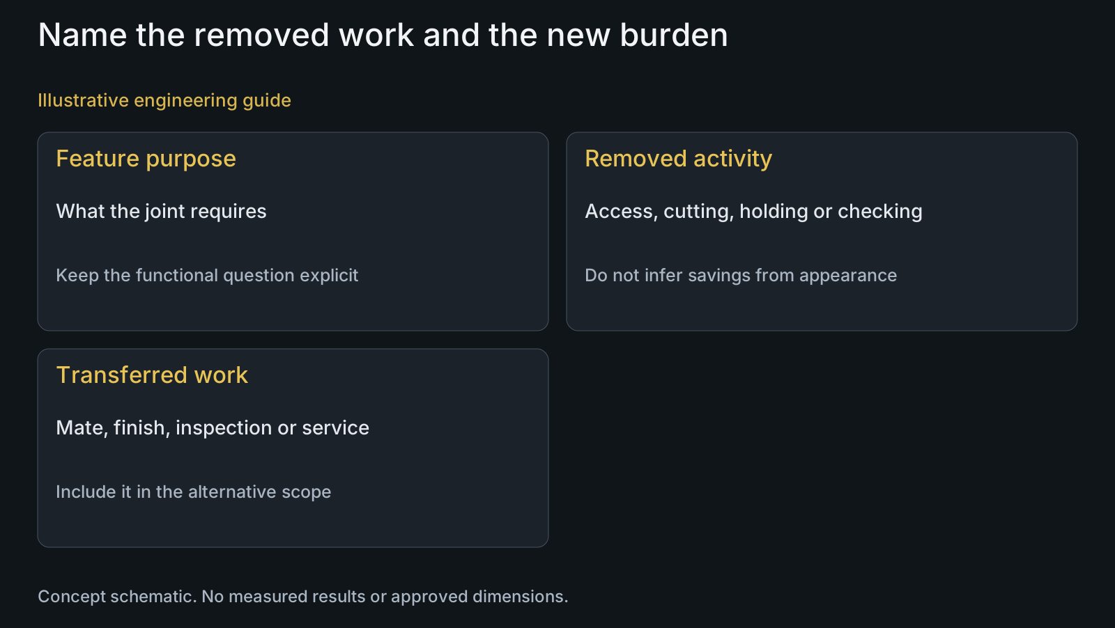
A standard thread or larger radius is an option, not a rule
A familiar thread designation may simplify sourcing of tools and gauges, but a nonstandard thread can serve a specific receiver or assembly requirement. Establish why it exists before proposing a change. Standardizing the bolt while leaving the receiver unchanged is not a coherent cost alternative.
Likewise, cutting-tool geometry influences internal corners and transitions. Protolabs discusses radii and tool access, but a pivot shoulder must also allow its mate to reach the intended contact. Do not increase a transition radius solely because a larger tool is convenient.
Include affected receivers, bearing chamfers and spacers in the marked proposal. A change that removes one machining activity but requires another component revision belongs to a system-level comparison. Preserve the earlier baseline so the purchasing decision does not hide that added work.
Relax a requirement only after identifying what it controls
Distinguish a noncontact exterior surface from a bearing seat, contact face or stack dimension. The useful question is not which numerical limit looks tight, but how variation in that feature affects the assembled relationship. Retain the functional limits and datum relationships needed for acceptance.
A clearer drawing can sometimes remove ambiguity without changing permissible geometry. Resolve conflicting size, model and general-note definitions before treating a manufacturing quote as evidence that tolerances are excessive. An unclear requirement and a difficult requirement are different problems.
Include the measurement consequence. A proposed profile may be simpler to cut but harder to inspect against its new definition. Specify the characteristic and represented final state so the total opportunity includes the needed verification rather than omit it from the revised price.
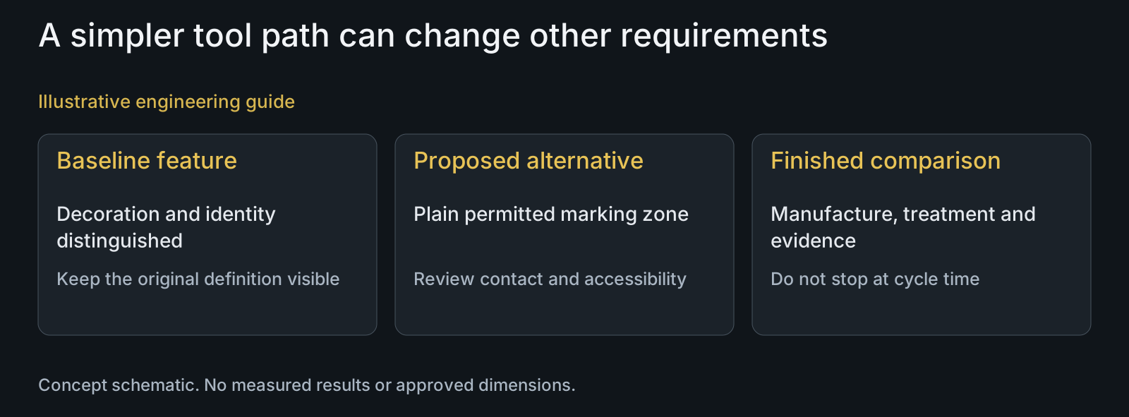
Review marking and finish alongside the machining change
Machined decorative text or a deep logo can create tool paths without serving the same task as identification. Establish what the marking must communicate, where it must remain readable and what method is permitted. A cosmetic simplification is not authority to remove required traceability or assembly information.
Protolabs identifies recessed text as potentially time-consuming machining work. That observation supports reviewing the requirement, not a universal promise that laser marking is cheaper or available for every surface. Agree the proposed method and location within the project's actual capability scope.
Carry the changed geometry through surface-treatment review, protection and packaging. A new contact or recessed area may need another processing definition. Compare those effects with the cost activity map before calling the shorter tool path a lower finished-kit cost.
Review example: shallow marking changes more than the tool path
Illustrative engineering example: assume a pivot axle includes a decorative recessed band and separately required readable identification. A proposal removes the decorative machining and provides a permitted plain marking zone. No actual cycle times, prices, supplier marking capacity or approved design are assumed.
The reviewer distinguishes decoration from required information, checks the proposed zone against contact and tool-access functions, and defines the permitted marking method. They then compare machining, final treatment, marking inspection and finished-kit protection on the same quantity basis.
If the proposed route introduces another operation or evidence requirement, that burden remains in the alternative offer. The decision may still favor the baseline. The lesson is to compare removed and added work openly, not to claim that every engraving should be deleted or that a shorter cycle guarantees a cheaper kit.
Questions buyers need to confirm
Which pivot dimensions should we relax first?
Start with functions, not numerical size. Identify noncontact geometry separately from seats, contact faces and stack controls. Review mating variation and measurement before proposing a particular changed limit.
Can shorter blind holes reduce machining cost?
They are possible candidates where functional depth and clearance remain sufficient. Identify usable thread overlap, bottom clearance and access purpose. A shallower modeled hole cannot be preferred merely because its tool path is shorter.
Should every nonstandard thread be replaced?
No. Establish its receiver and application purpose, then compare a coherent bolt-and-mate alternative. Tool or gauge convenience does not approve an incompatible receiver or altered engagement.
Is a larger radius always easier and safer?
Not as a blanket conclusion. Tool access may improve, but the mate must still reach the intended contact and the transition must satisfy design requirements. Review the actual envelope rather than copy a general machining limit.
Can required marking be removed to reach the target price?
Only if the design owner changes the requirement appropriately. Distinguish decorative machining from identity or assembly information. Review permitted methods, location, readability and final finish before pricing a different marking scope.
Does a reduced cycle guarantee a cheaper complete kit?
No. New inspection, marking, finishing, fixtures or mating-part work can offset it. Compare the same finished unit, quantity and evidence scope, with removed and added activities explicitly identified.
Technical references and scope
Protolabs machining tips for complex features. General tool-reach, deep-feature, radii and recessed-text considerations. Vendor-specific limits, equipment, insert-life claims and service promises not adopted.
Explore related component, material and sourcing decisions in the customer decision knowledge center. For a drawing review, use the Drawing/BOM RFQ path.
Review a specific feature-level cost alternative
Send the baseline drawing and STEP, mating parts, functional zones, material and finish, required identification, quantities and marked candidate changes through the Drawing/BOM RFQ path. PremFixer can review which manufacturing activities may change and what interface or acceptance decisions remain with your team.
Discuss the drawing and BOM