
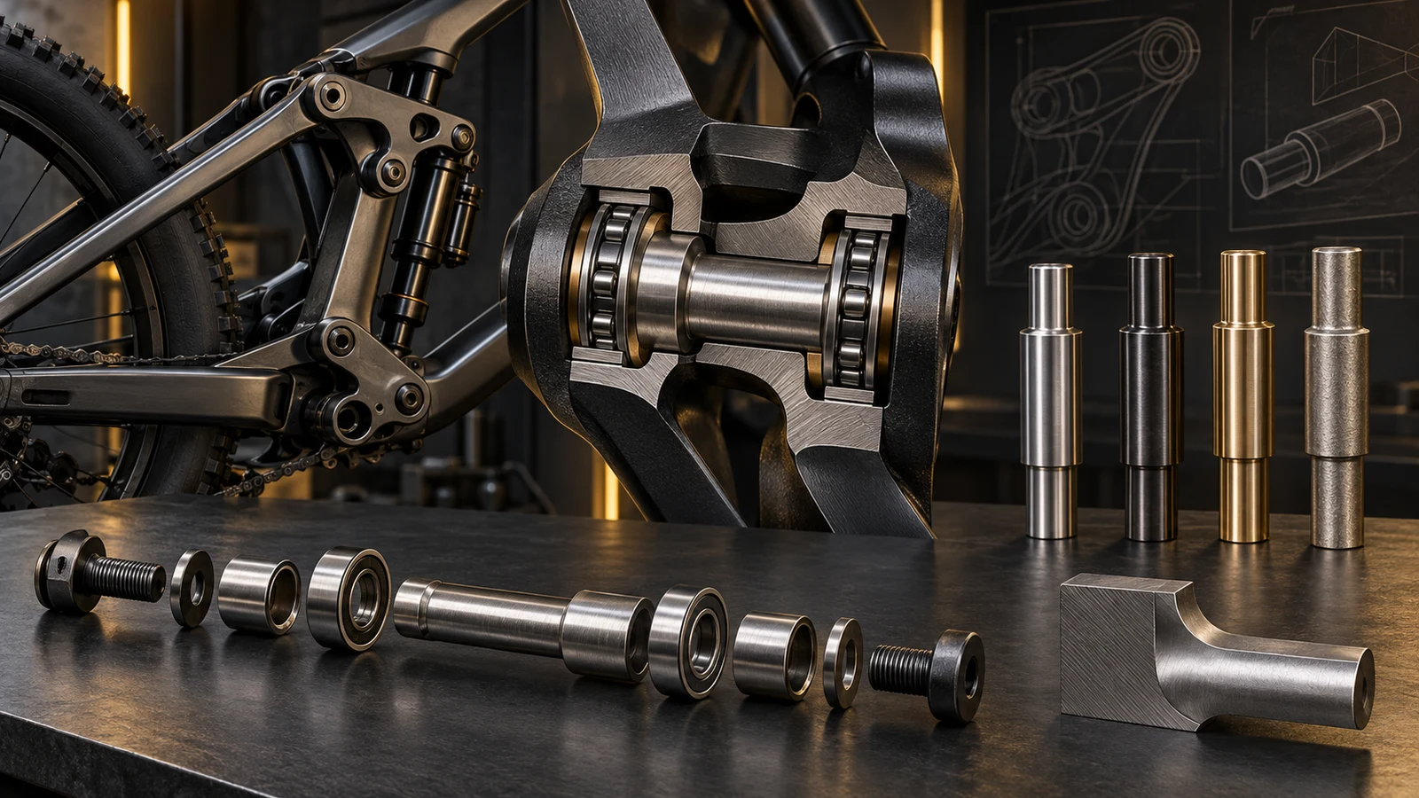
A suspension linkage pivot can fail despite an attractive alloy fatigue value because the finished component does not reproduce the material test specimen or its conditions. Locate the affected shaft or retaining feature, then connect its geometry, support, moving contacts and assembly state to the relevant loading. Do not start by declaring titanium, steel or another material the cure. A material change may leave the same critical transition or interface unresolved. PremFixer can review a drawing-defined manufacturing candidate; the responsible product team needs the applicable failure or validation evidence to determine whether material, geometry, surface or assembly changes address the actual concern.
Hero: concept illustration of example hardware and its application. It is not a factory photograph, tested component or approved production geometry.
Identify which linkage position and feature are involved
Upper-link, lower-link and main-pivot hardware are not interchangeable engineering cases. Record the represented frame configuration, joint position and component identity. Mark the shaft, retaining screw, sleeve and bearing or bush arrangement so a report does not use pivot bolt to mean several different parts.
If a failure is being investigated, retain the affected components and their identity through the responsible examination process. Record where separation or damage is observed and what is known about assembly and service history. A photograph can locate a concern but does not establish its cause or a material defect.
If there is no failure, state the design question instead: a proposed transition, support arrangement or material candidate. Do not write an investigation narrative for an untested design. The useful comparison begins with one named joint and concern, not a claim that all linkage bolts are prone to break.
Read material fatigue data within its test conditions
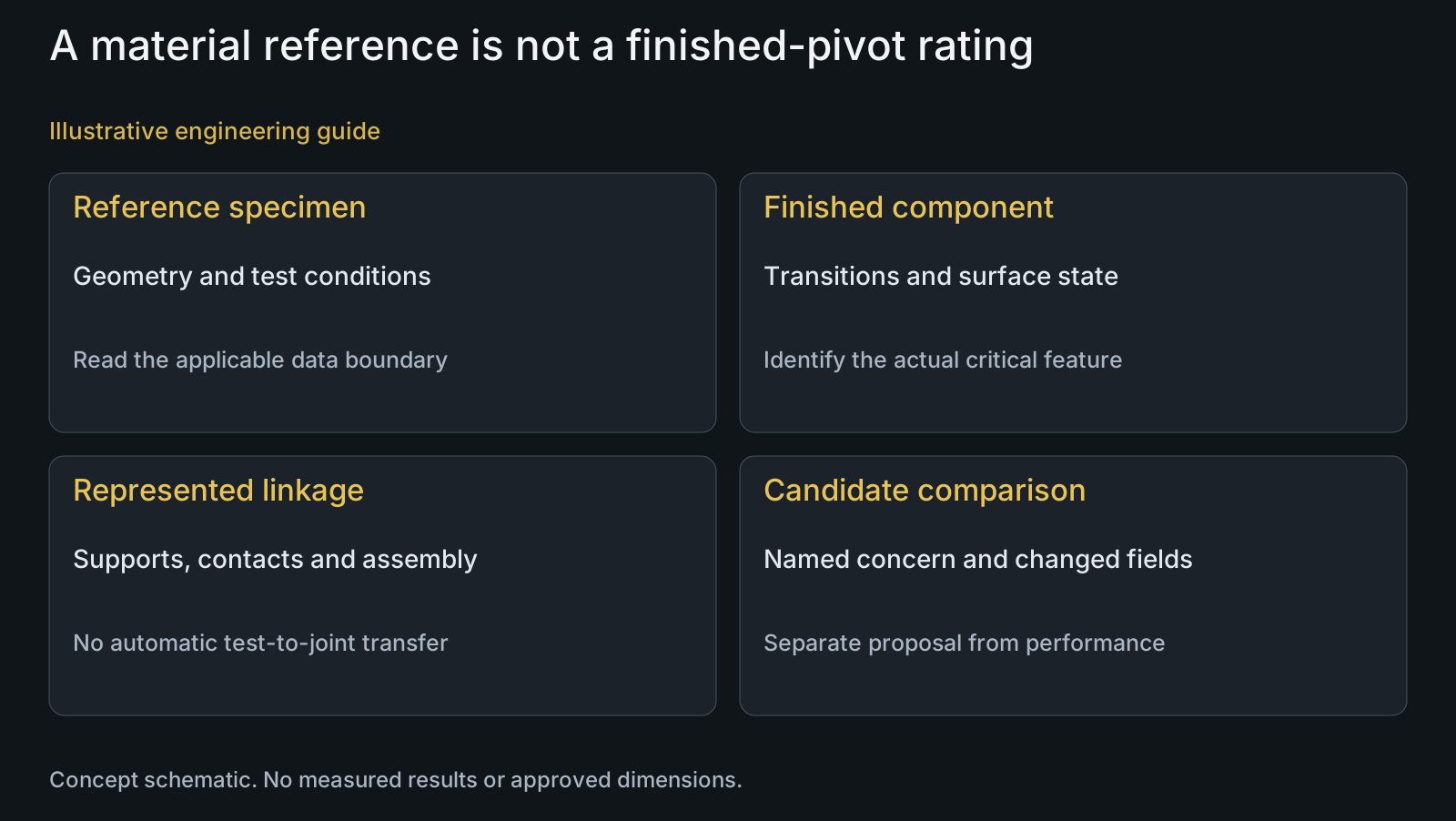
Published fatigue data needs the specimen, loading mode, stress conditions, surface and evaluation criterion that accompany it. ASTM E466's public description identifies material, geometry, surface condition and stress as variables in axial fatigue evaluation. An isolated strength value cannot describe an unspecified finished linkage component.
Ask whether the reference concerns a material specimen, a machined component or an assembled joint. Keep those evidence levels distinct. A value from one material condition or test arrangement does not establish an application life, universal endurance threshold or accepted substitution.
Use the axial and bending fatigue guide to frame the evidence question. This article does not assign a universal fatigue value to TC4 or promise that any titanium shaft lasts longer than the existing part.
| Concern or proposal | Useful comparison | Risk | Evidence needed |
|---|---|---|---|
| Published alloy fatigue value | Specified reference versus actual component | Treating a specimen value as bolt life | Loading, condition and geometry context |
| Damage near a transition | Material-only versus geometric candidate | Declaring cause from location alone | Component examination and represented assembly |
| Support or locating region | Existing versus revised relationship | Changing shaft material but retaining the concern | Joint geometry and applicable loading |
| Surface requirement change | Same feature and final state | Appearance used as performance proof | Specified surface and relevant evaluation |
| Assembly-state concern | Defined clamp versus moving contact | Using preload as one universal adjustment | Stack, receiver and approved method |
| Proposed material substitution | Controlled condition and manufacture | Quote treated as application approval | Candidate definition and validation scope |
Connect the critical feature to its support and contact
Engineering analysis: examine the shoulder, under-head transition, thread start and contact regions in the represented assembly. Identify which features are near the concern and what surrounds them. A material-only proposal leaves those geometrical relationships unchanged unless a new drawing says otherwise.
Review support spacing, bearing or bush position and the shaft's locating region together. Check whether a proposed transition can clear the mating edge while preserving its required function. Changing a fillet without considering the adjacent spacer or ring can create a different interface question.
The fillet and chamfer guide separates transition geometry from edge clearance. Do not copy a universal radius or label a region critical without a basis. Feature identity makes the material comparison traceable to the actual joint.
Keep clamp force and bearing adjustment distinct
Show which faces transmit the intended clamp and which surfaces are meant to move. Include spacer order, shoulder length, receiver and mating materials. The word preload is ambiguous if it does not identify the loaded relationship and the assembly method.
SKF describes matched bearings and spacer arrangements as ways of setting preload or clearance in its paired angular-contact examples. This demonstrates arrangement dependence, not a bearing choice or adjustment recipe for a bicycle linkage. Do not transfer its high-speed bearing values to a pivot.
For an unresolved looseness or movement complaint, the linkage-play article covers assembly fit. Here the narrower decision is whether a proposed material change addresses the named concern under the defined assembled state. More tightening is not a substitute for understanding that state.
Compare candidates without changing the evidence boundary
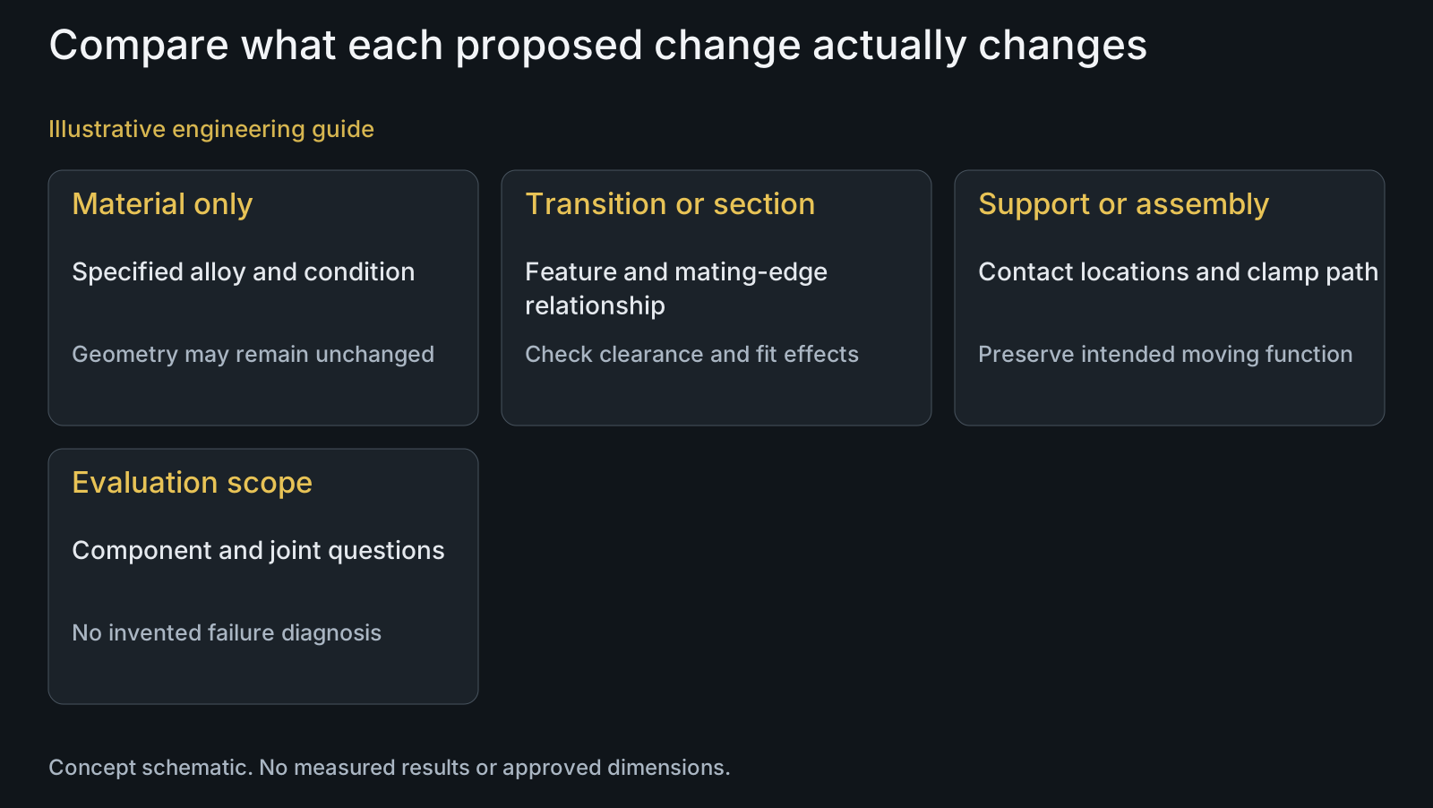
A useful comparison can include a specified material condition, revised section or transition, changed support relationship, or controlled surface requirement. State what each candidate changes and what it retains. Avoid ranking materials by one published number while silently changing geometry or assembly conditions.
Manufacturing review should identify the finished features and treatment state the candidate drawing requires. Discuss material availability and machinability through materials and CNC turning. Distinguish a proposed processing route from evidence that the component meets the application requirement.
Agree which component and assembly evaluations address the concern and what comparison they permit. A dimensional report demonstrates the measured features, not a fatigue improvement. No owned fatigue laboratory, completed test or accepted frame redesign is implied by a quotation discussion.
Review example: alloy change with the same shoulder transition
Illustrative engineering example: assume a team proposes a titanium shaft after receiving a report of damage near a linkage shoulder. It has a component drawing and assembly view but no verified failure cause or applicable fatigue comparison. No real incident or test result is represented.
The reviewer locates the reported region, checks its relation to the support and mating edge, and separates known geometry from unknown service conditions. It compares a material-only candidate with a transition or support candidate rather than declaring either one the solution.
The resulting review identifies which fields and evaluations would distinguish the proposals. It keeps the reported damage separate from an established mechanism and the material reference separate from component performance. The decision can advance without inventing a fatigue limit, lifetime or confirmed improvement.
Questions buyers need to confirm
Can a high alloy fatigue value guarantee linkage bolt life?
No. Identify the reference specimen, loading, material condition, surface and evaluation criterion. Compare those with the finished component and represented joint. A standalone value cannot establish life under unspecified bicycle service conditions.
Should titanium be the first response to a broken pivot?
Not automatically. Locate the affected part and preserve the examination evidence, geometry and assembly history. Compare the proposed material with the identified concern; changing alloy may leave the same transition, support or contact relationship unresolved.
Does damage near a shoulder prove the fillet was wrong?
No. Location identifies an examination area, not a cause by itself. Review the actual transition, mating clearance, support, surface condition and available loading or service evidence. Do not prescribe a universal radius from a photograph.
Are bolt preload and bearing preload the same instruction?
Not necessarily. Show the clamp path, spacer stack, bearing or bush arrangement and intended moving surfaces. The loaded relationship and adjustment method need to be explicit; do not use the word preload as a universal tightening remedy.
Can a dimensional inspection establish fatigue improvement?
No. It supports conformity of the measured features in the stated condition. Performance comparison needs the relevant component or assembly evaluation with its loading and criteria. A drawing-conforming sample is not a proven lifetime improvement.
What inputs help a linkage material review?
Send the component and assembly drawings, STEP model or represented sample, joint position, BOM and quantities. Include support and spacer arrangement, receiver, material condition, finish and installation information. Add any authorized failure evidence or validation plan, with unresolved causes identified.
Technical references and scope
ASTM E466 public significance and use. Public description of material, geometry, surface and stress variables in axial fatigue evaluation. No paid procedure, universal fatigue limit or component life asserted.
SKF paired bearing preload and clearance explanation. Arrangement-specific matched bearing and spacer examples. No angular-contact selection, numerical preload or high-speed result transferred to a bicycle pivot.
Explore related component, material and sourcing decisions in the customer decision knowledge center. For a drawing review, use the Drawing/BOM RFQ path.
Compare linkage materials at a defined feature and joint
Send the linkage position, assembly and component drawings, STEP data or represented samples, BOM and quantities. Identify the concern and any available examination or validation evidence, plus material condition, surfaces and assembly instructions. PremFixer can review manufacturing candidates while material data, failure conclusions and application approval remain separate.
Discuss the drawing and BOM