
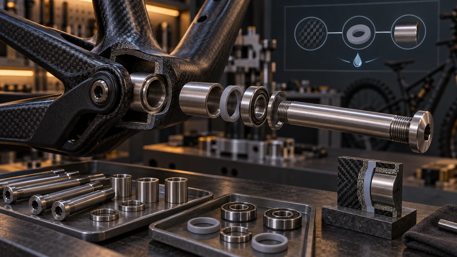
Changing a pivot bolt to titanium does not by itself approve corrosion compatibility with a carbon frame. Review the complete conductive contact path, including metal inserts, bearing rings, spacers and contact hardware, together with moisture exposure and the specified barriers. The buyer is deciding whether a proposed material, coating or geometry change preserves the intended protection and mechanical arrangement. Galvanic concerns in a conductive carbon-composite assembly need not appear as damage to the titanium bolt; connected metal can be the relevant component. No universal voltage difference or corrosion-free pairing is established here. Treat isolation as a defined assembly requirement that must survive manufacture, installation and permitted service.
Hero: concept illustration of example hardware and its application. It is not a factory photograph, tested component or approved production geometry.
Identify conductive contacts and moisture paths
The FAA's aircraft corrosion guidance describes galvanic interaction through electrical contact and an electrolyte. Its composite discussion includes graphite/epoxy in multicomponent couples. These are bounded corrosion principles, not bicycle certification rules, a pivot corrosion rate or a universal material-pair ranking.
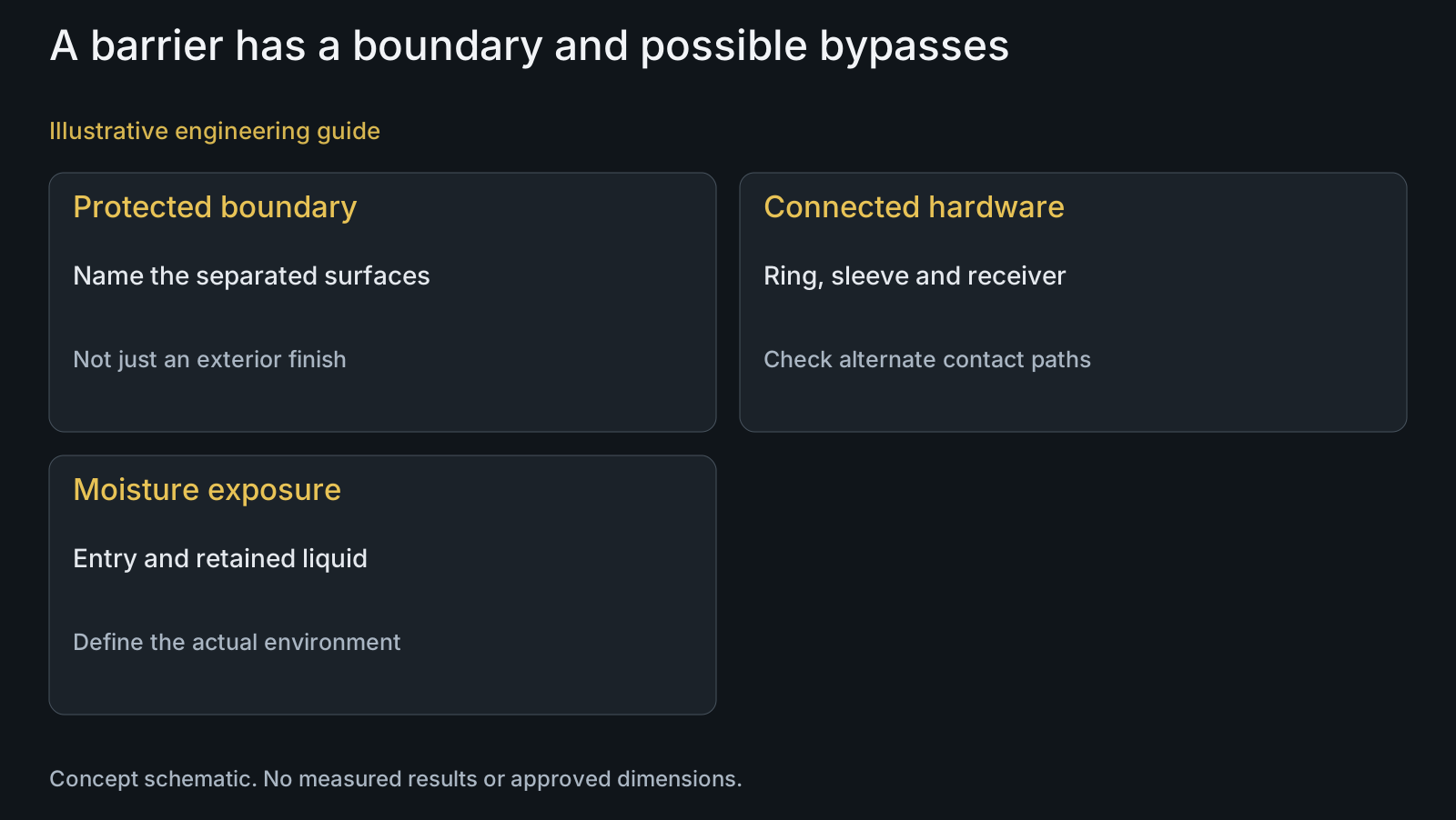
For the actual joint, map which exposed conductive surfaces are connected through the axle, receiver, ring or sleeve. Then identify where moisture can reach those surfaces or remain in a crevice. An exterior carbon appearance and a titanium label do not reveal the hidden contact arrangement.
The titanium carbon-frame interface guide addresses initial material and mechanical compatibility. This article concentrates on retaining the intended barrier arrangement when hardware, surfaces or assembly details change. Begin from the existing defined interface, not from a general promise about titanium.
Assign a function to each proposed protective layer
Electrical isolation, moisture exclusion and a specified surface finish answer different questions. Identify which layer serves which function, its location and the surfaces it must separate or protect. A ring intended to distribute contact is not automatically an electrical barrier, and a seal does not by name establish complete isolation.
The FAA composite section discusses nonconductive layers and warns that a compromised seal can conceal corrosion. Do not copy its aircraft materials or repair procedures into a bicycle specification. The useful buyer question is whether the chosen protection remains effective at the actual assembled boundaries.
Require the design to explain potential bypasses: a metallic ring bridging the protected region, exposed insert edges, a conductive sleeve contact or a changed fastener face. A barrier under one face cannot be credited with isolating every other connected path without reviewing them.
| Proposal | Function to establish | Possible unresolved issue | Useful verification |
|---|---|---|---|
| Titanium axle substitution | Specified hardware material | Other connected metal still exposed | Complete conductive contact map |
| Nonconductive ring | Isolation at named boundary | Alternate contact bypasses it | Section, boundary and assembled contact |
| Seal arrangement | Specified moisture exclusion | Compromised seal conceals a contact | Defined continuity and access review |
| Different coating | Required final surface state | Internal or later-cut surface uncovered | Delivered feature and route review |
| Wider contact ring | Intended supported footprint | Barrier bridge or stack change | Combined contact and geometry comparison |
| Permitted service replacement | Restoration of defined configuration | Protected layer altered during removal | Responsible restoration instructions |
Control the geometry as well as the barrier material
A barrier or washer can alter the axial stack, supported footprint, clearance and effective engagement. Compare those dimensions with the intended contact and retention arrangement. Do not choose an unspecified isolation component solely because it is electrically nonconductive.
Identify how the proposed layer behaves under the defined assembly condition and how its boundary is located. Material suitability for contact and retained function requires evidence for the actual requirement. No polymer creep allowance, composite pressure limit or tightening torque is assigned from a generic material name.
Use the joint integration review for locating, clamping and tool access. A corrosion-protection proposal still needs those mechanical relationships. Changing the contact ring to make a barrier easier to install can move another critical contact rather than preserve the original assembly.
Review final surfaces and the operations that can change them
Mark the relevant protected, masked and contact surfaces on the drawing. Identify the delivered condition required for each, including edges and areas reached during assembly. An external finish color cannot establish coverage or continuity at a concealed thread, bore or contact face.
Connect the requirement to the proposed surface-treatment route. Finishing, later machining or a change in contact geometry can affect the surface being credited with protection. Verify the specified final condition rather than carrying forward approval of an earlier unfinished sample.
Keep assembly and service restrictions explicit. If a permitted removal or replacement operation changes a barrier, state the required restoration and verification under the responsible frame instructions. This is a design-review question, not permission to improvise a sealant, add washers or clear a used frame for riding.
Select verification that examines the represented interface
A review of loose parts can confirm specified geometry or surface details within its scope. It cannot establish all concealed contacts after tightening. Define which assembled locations need examination and whether the represented configuration includes the intended insert, barrier and neighboring components.
Environmental evaluation needs the actual exposure question, specimen construction and acceptance basis. A finish-only coupon or a result from an unrelated joint does not automatically cover a multicomponent frame interface. No test duration, accelerated-to-service conversion or demonstrated protection result is supplied here.
When proposing a material or finish substitution, identify the connections it changes and retain responsible design approval. PremFixer's manufacturing scope supports drawing-defined hardware and coordinated specified processes, not hidden composite construction approval or a corrosion-free service guarantee.
Illustrative review: a substituted contact ring
Illustrative engineering example: assume a carbon-frame pivot uses a titanium axle, metal insert and a defined isolation ring. A sourcing proposal replaces the contact ring with a wider metallic version while keeping the axle drawing unchanged. No real frame, corrosion observation or validated protection scheme is represented.
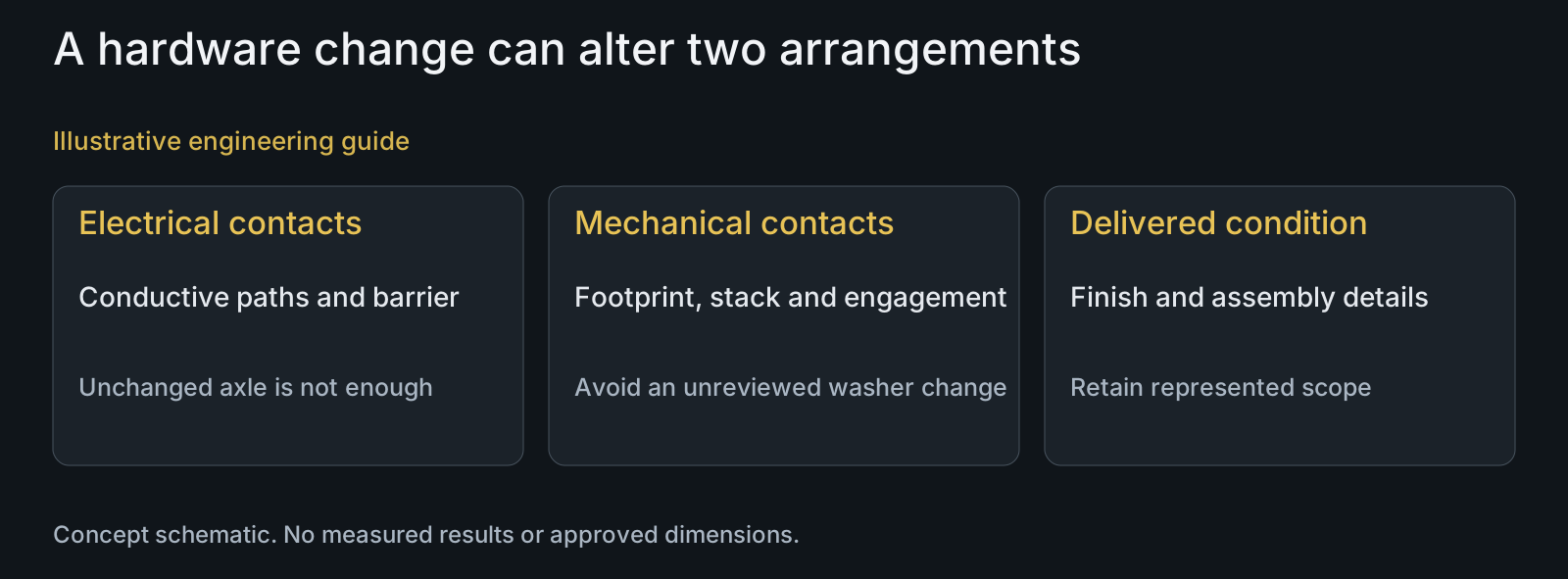
The review asks whether the wider ring bridges the protected boundary or creates a new conductive contact. It also examines its axial position, supported footprint and tool access. The unchanged titanium axle does not establish that the assembly's electrical or mechanical arrangement is unchanged.
If the drawing does not identify the ring's mating surfaces and barrier extent, the substitution remains unresolved. The next useful inputs are the revised section, material and surface definitions, assembly condition and intended exposure review. This example reports neither a failure nor successful protection; it identifies the decisions a material-only comparison misses.
Questions buyers need to confirm
Does titanium make every carbon-frame pivot corrosion-free?
No such guarantee is established here. Identify the connected conductive materials, electrolyte exposure, protected surfaces and retained contact arrangement. The relevant affected member may be an insert or neighboring hardware rather than the titanium axle.
Is an insulating washer enough to approve the interface?
Not by itself. Locate the boundary it separates and check other contacts that may bypass it. Review footprint, stack, engagement and behavior under the specified assembly condition as separate mechanical requirements.
Does a sealant automatically provide electrical isolation?
Do not infer that from the name. Identify its specified role, properties, coverage and assembled condition, and retain the responsible design instructions. Moisture exclusion and electrical separation are different functions; a compromised seal can also conceal the underlying contact.
Can the coating color prove that an internal contact is protected?
No. Define the particular surface, required layer and final processing state. Color on an exterior face cannot establish internal coverage, continuity, masking or the condition after later machining and assembly.
Does an unchanged titanium axle allow a different ring or insert?
Not automatically. Compare the new material, geometry, conductive contacts, barrier extent and mechanical stack. A sourcing substitution can change the protected assembly even when the axle part number remains unchanged.
What should an isolation-related RFQ include?
Provide the assembly section and STEP, material and finish details for each contact, barrier extent, mating BOM, retention condition, intended exposure and permitted service requirements. Identify unconfirmed hidden contacts so manufacture is not mistaken for composite-frame approval.
Technical references and scope
FAA AC 43-4B, galvanic corrosion and organic composites. 2018 aircraft guidance, sections2.5.3 and4.7.7, on conductive/electrolyte contact, composite multicomponent couples, nonconductive layers and compromised seals. General principles only; no bicycle compliance rule, aircraft repair recipe or numerical corrosion prediction transferred.
Explore related component, material and sourcing decisions in the customer decision knowledge center. For a drawing review, use the Drawing/BOM RFQ path.
Review the protected interface before substituting hardware
Send the current and proposed assembly sections, drawings and STEP, mating BOM, material and surface definitions, barrier requirements and intended exposure through the Drawing/BOM RFQ path. PremFixer can review the defined hardware and processing implications; frame-interface acceptance and service instructions remain with the responsible design authority.
Discuss the drawing and BOM