
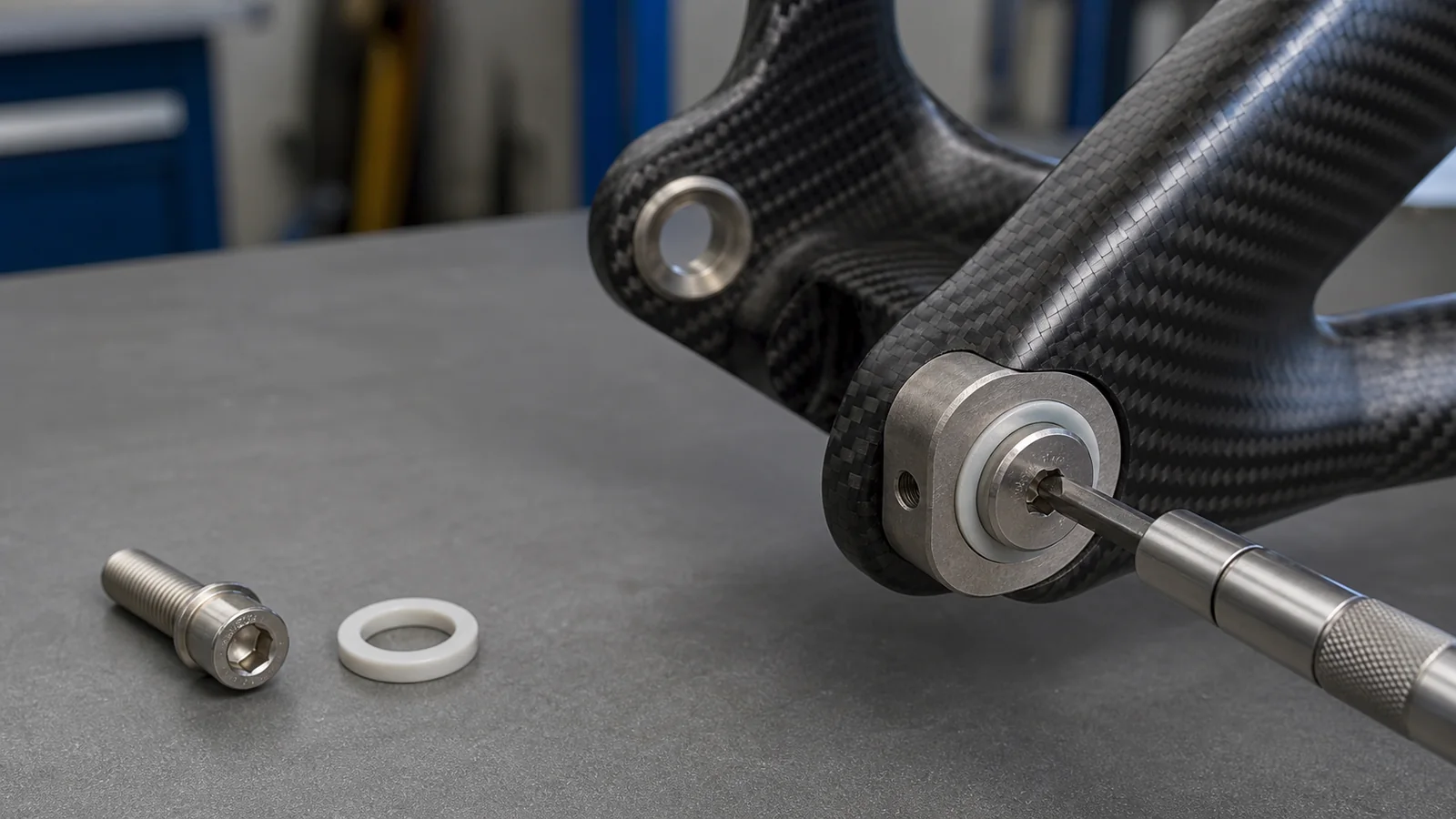
Carbon bicycle frame insert with an isolated metal fastener interface
Engineering case file · PF-CS-01

Carbon Frame Fastener Interface Validation

A standards-aligned review of preload, bearing area, and damage controls at a carbon-frame joint

All engineering case files
Record
PF-CS-01
Revision
R1
Published
31 Jul 2026
Scope
Methodology
Published engineering methodology

Methodology public; customer results confidential. This page explains the review structure and evidence gates without presenting unapproved customer data as a proven result.

01

The engineering decision in context

ApplicationFastened carbon-frame interface
Reported riskLocal assembly damage near an insert
Engineering directionControlled bearing area and installation preload
Public releaseMethodology public; customer results confidential
02

How should the complete joint stack be controlled so that installation preload is sufficient without creating an unverified local load path in the laminate or insert?

The anonymized brief concerns local damage observed near a fastener interface. The engineering hypothesis is that the outcome is governed by the full load path: laminate schedule, insert geometry and bond, washer or flange diameter, edge distance, surface flatness, friction, fastener stiffness, joint relaxation, tool accuracy, tightening sequence, and operator access.

A larger flange can reduce nominal contact pressure, but it may also introduce edge loading or interference. “Anti-crush” is therefore treated as a design objective, not a transferable product claim.

03

Controls, records, and release gates

The acceptance requirement is fixed before testing. Each record must identify the drawing revision, sample, method, and decision owner.

ControlMethod basisRecord requiredRelease gate
Joint definition Released laminate, insert, fastener, washer, and mating-part stack with tolerance analysis Controlled drawings, laminate specification, and insert or bond-process record The evaluated stack matches the production design
Bearing and preload Engineering calculation or simulation followed by torque-to-preload correlation on representative joints Material inputs, contact area, assumptions, and torque-angle or clamp-force data The approved installation window avoids observed damage and insufficient clamp load
Assembly study Torque ramp and repeated assembly using production tools, sequence, and access Tool calibration, operator method, sample count, inspection images, and outlier review Process limits and a reaction plan are defined
Damage inspection Customer-selected visual, tap, ultrasonic, sectioning, microscopy, or other suitable method Detection sensitivity, acceptance definition, before-and-after evidence, and reviewer decision No damage-reduction claim without a defined detection method and result
System validation ISO 4210-2:2023 requirements and ISO 4210-6:2023 methods where applicable, plus customer load cases Subassembly or frame proof and fatigue report with approved deviations The complete frame application meets its release plan
04

What makes the decision traceable

  1. 01

    Freeze the drawing revision, laminate, insert, joint stack, and surface condition.

  2. 02

    Correlate tool torque with preload on representative assemblies.

  3. 03

    Inspect the joint with a method whose sensitivity and acceptance limits are defined.

  4. 04

    Record the reviewer’s disposition and obtain customer approval for any public result.

What this public record does—and does not—establish

This public file documents the engineering method and decision logic. It does not claim a damage-free joint, a universal flange size, a torque value, fatigue life, or production yield. Those conclusions require project-specific evidence for the exact laminate, insert, and assembly process.