
Rotating-bending fatigue is not an automatic explanation for a bicycle hub axle failure. First identify the failed axle, retention bolt or other component, then establish what rotates and how loads reach its supports. A hub shell can rotate around an axle whose angular position is constrained; that axle may still see changing forces. Preserve the failed hardware and compare the damage location with its geometry, installed contacts and service history. For an OEM deciding whether to change the part or commission testing, the useful starting point is a representative load-and-support definition, not a blanket recommendation for rolled threads or shot peening.
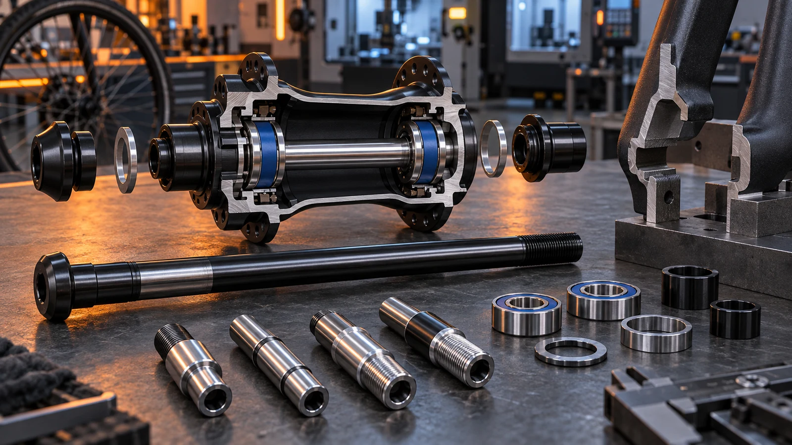
Hero: concept illustration of example hardware and its application. It is not a factory photograph, tested component or approved production geometry.
Separate wheel rotation from the axle's stress history
Use an assembly section to identify the hub shell, bearing rings, central axle, end caps and wheel-mounting hardware. Mark each component's motion relative to the frame or fork. Avoid the ambiguous label hub bolt when the ordered part could have a retention function rather than carry the same loads as the axle.
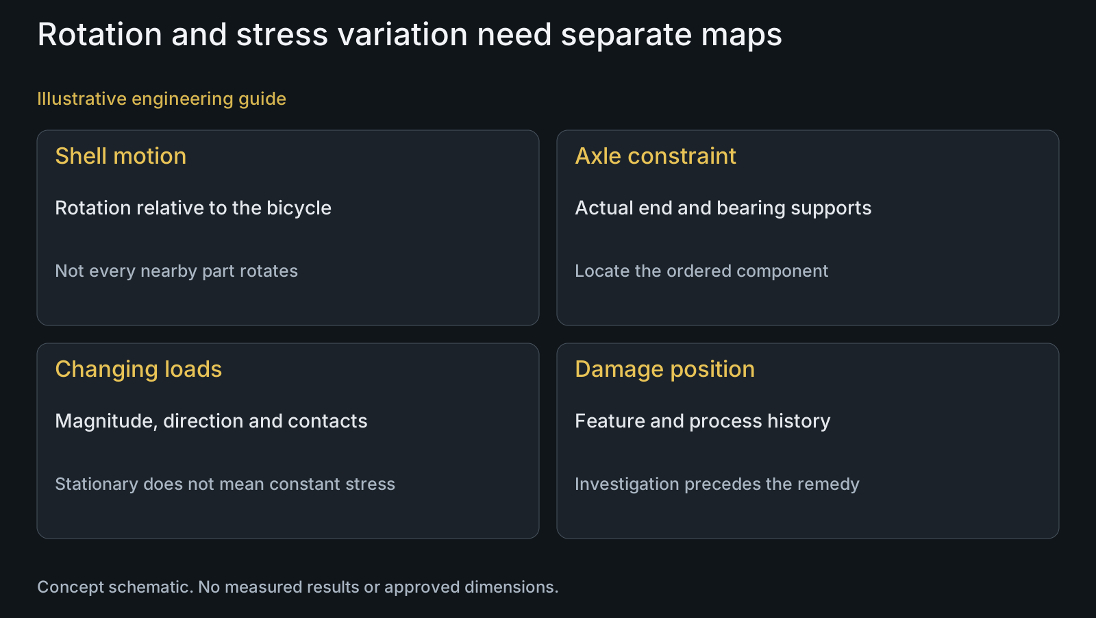
Engineering analysis: a rotating member under a transverse load fixed in space can experience a changing bending direction relative to its material. A non-rotating member does not acquire that exact condition merely because a neighboring shell rotates. Its stress can nevertheless change when load magnitude, direction or contact changes during use.
The stainless hub hardware guide covers component identity and material specification. Here the decision is narrower: which motion and load history should a failure investigation or evaluation represent? Neither visible rotation nor the absence of rotation supplies the complete answer.
Draw the supports and the installed contact state
Locate bearing contacts, axle shoulders and frame or fork constraints along the component. Show where forces enter and which surfaces provide reactions. Include overhung features and section changes rather than reducing the assembly to nominal axle diameter.
DT Swiss explains that its hub design accounts for the wheel-mounting clamp force and its effect on axle compression and bearing behavior. This manufacturer-specific example shows that the installed contact state matters; it is not an adjustment procedure or a universal construction rule for other hubs.
If a test holds the component at different positions from the bicycle assembly, document that difference. As an engineering assessment, changing the support arrangement can change the bending distribution even when the applied force is unchanged. Compare the represented contacts before interpreting a laboratory result as evidence for the actual part.
| Observed condition | Decision input | Unsupported shortcut | Useful review or evaluation |
|---|---|---|---|
| Shell rotates around constrained axle | Separate component motion and changing loads | Every hub part has rotating-bending duty | Assembly motion and load map |
| Damage near a support transition | Support position and final geometry | Specify a stronger alloy immediately | Feature-level geometry and evidence review |
| Damage in a threaded region | Actual thread, engagement and loading | Rolling cures all axle failures | Defined process comparison for that feature |
| Behavior changes when installed | Mounting clamp and end contacts | Bench state equals service state | Represented installed configuration |
| Axial material fatigue result | Specimen and test scope | Hub assembly life is established | Explicit applicability and component evidence |
| Proposed rotating test | Member motion and fixture supports | Wheel rotation alone justifies the method | Compare fixture with actual load boundaries |
Use damage location to narrow the investigation
Record which feature is damaged: a threaded region, shoulder transition, bearing seat, end contact or another location. Keep photographs tied to part orientation and retain the mating components. A broken axle and a loose end-retention screw are not interchangeable observations.
Preserve installation, revision and process history alongside the parts. Do not polish or alter a fracture surface before the responsible investigator determines what evidence is needed. A photograph can locate damage, but it cannot by itself establish the loading mechanism or rule out other contributing conditions.
Compare the damaged feature with the proposed load path and the drawing's final surface state. The fillet and chamfer guide distinguishes transitions that serve different functions. Its geometry questions can support review, but they do not diagnose a hub failure without the actual interface and evidence.
Choose evaluation that answers the component question
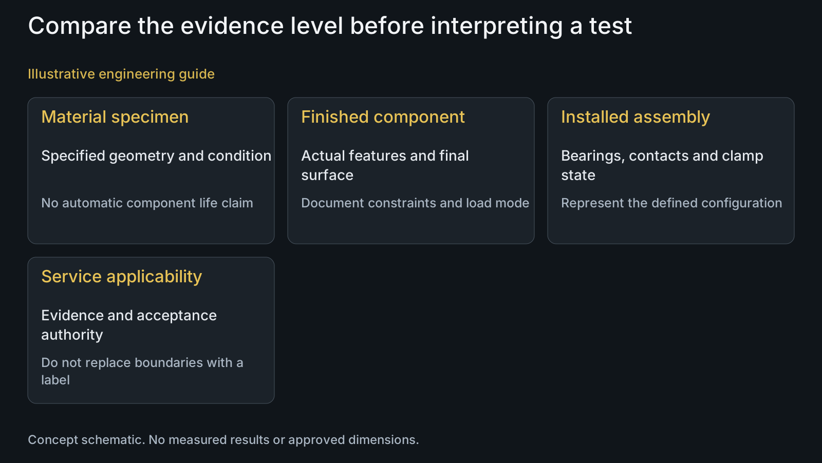
State whether the immediate question concerns material behavior, a finished component or the installed hub assembly. These are different evidence levels. ASTM E466 describes force-controlled constant-amplitude axial fatigue testing of metallic materials; its public scope does not make such a test a bicycle hub durability approval.
For a component assessment, define constraints, loading mode, mean and varying load components, relevant geometry and final manufacturing condition. For an assembly assessment, include the contacts and installation condition being represented. The responsible engineering team should specify the method and acceptance basis rather than selecting a test from the application name.
Use the axial and bending fatigue guide to distinguish test purposes. An axial material result cannot silently become rotating-bending evidence, and a rotating fixture cannot compensate for an undefined service-load relationship. No fatigue life or universal load level is established here.
Make a process change address an identified feature
Rolled threads and shot peening are proposed processes, not an automatic cure for every axle fracture. Identify the feature they are intended to affect and the final requirements they must preserve. If the damage is elsewhere, explain why changing the thread process is expected to answer that observation.
Compare the actual component through CNC turning, its specified material condition and any drawing-defined surface route. State which characteristics will be measured after processing. Do not infer an improvement percentage or a supplied shot-peening capability from a general process label.
A changed manufacturing route may warrant a comparative evaluation, but the comparison must retain the relevant component geometry and assembly boundaries. Changing support positions at the same time as the process would leave the cause of any observed difference unresolved. This is an analysis principle, not a claim of completed PremFixer hub tests.
Review example: a rotating wheel with a constrained axle
Illustrative engineering example: assume a hub shell turns on cartridge bearings around an axle constrained by its end interfaces. A proposed replacement changes a shoulder transition near one bearing support. No dimensions, crack diagnosis or measured life are supplied.
The reviewer maps the constrained axle separately from the rotating shell and identifies how the changed transition relates to the support. A proposal to spin a generic round specimen would need an explicit explanation of what it represents. The team instead defines the component question and the necessary support and load relationship before choosing a method.
The review leaves a drawing-level comparison and an evaluation scope for the responsible product team. It does not prove the new transition is better or declare shot peening necessary. The valuable distinction is between reproducing visible wheel motion and representing the ordered component's stress conditions.
Questions buyers need to confirm
Does a hub axle rotate whenever the wheel rotates?
Not necessarily. Establish the axle's motion relative to the frame or fork from the actual assembly. The hub shell can rotate around a constrained axle. Assess changing loads separately rather than assigning fatigue duty from wheel motion alone.
Can a stationary hub axle experience fatigue?
Yes, variable stress does not require the part itself to rotate. Identify changes in force magnitude, direction, contacts and installation state. Whether those conditions explain a particular failure requires the component and its evidence, not this general distinction.
What is the most useful first record of an axle fracture?
Identify the damaged part, orientation and feature, and preserve it with the mating components and service history. Record the drawing revision and manufacturing condition. Avoid treating a photograph as a completed mechanism diagnosis or altering evidence before specialist review.
Will rolled threads and shot peening prevent hub axle failure?
No universal prevention claim is supported. Identify the damaged feature and proposed process scope, then define the comparison and final requirements. A thread change may not address damage at another support or transition, and process suitability needs its own evidence.
Does an axial fatigue test approve the complete hub?
No. Read the method and specimen scope. An axial material result, a finished-component result and an installed-assembly result answer different questions. State how the evidence relates to the actual loading and contacts before using it for a product decision.
What should a hub axle fatigue RFQ or review request include?
Send the ordered part and assembly drawings, STEP or represented samples, bearing and end interfaces, BOM, material condition, finish and quantities. Include the motion/load definition, observed damage and relevant history if available. Identify the proposed manufacturing change and the responsible evaluation authority.
Technical references and scope
DT Swiss bearing technology. Manufacturer-specific explanation of wheel-mounting clamp effects on axle compression and bearing behavior. No universal hub adjustment instruction or compatibility claim.
ASTM E466 public scope. Force-controlled constant-amplitude axial fatigue testing of metallic materials, not a complete bicycle hub approval or rotating-bending method.
Explore related component, material and sourcing decisions in the customer decision knowledge center. For a drawing review, use the Drawing/BOM RFQ path.
Review hub axle manufacture against the real load and support definition
Send the part drawing, STEP or represented sample, hub section, bearing/end contacts and BOM with material condition, finish and quantities. Include available motion and load information, damage records and any proposed process change. PremFixer can review manufacturability while the failure diagnosis, test scope and application acceptance remain explicit.
Discuss the drawing and BOM