

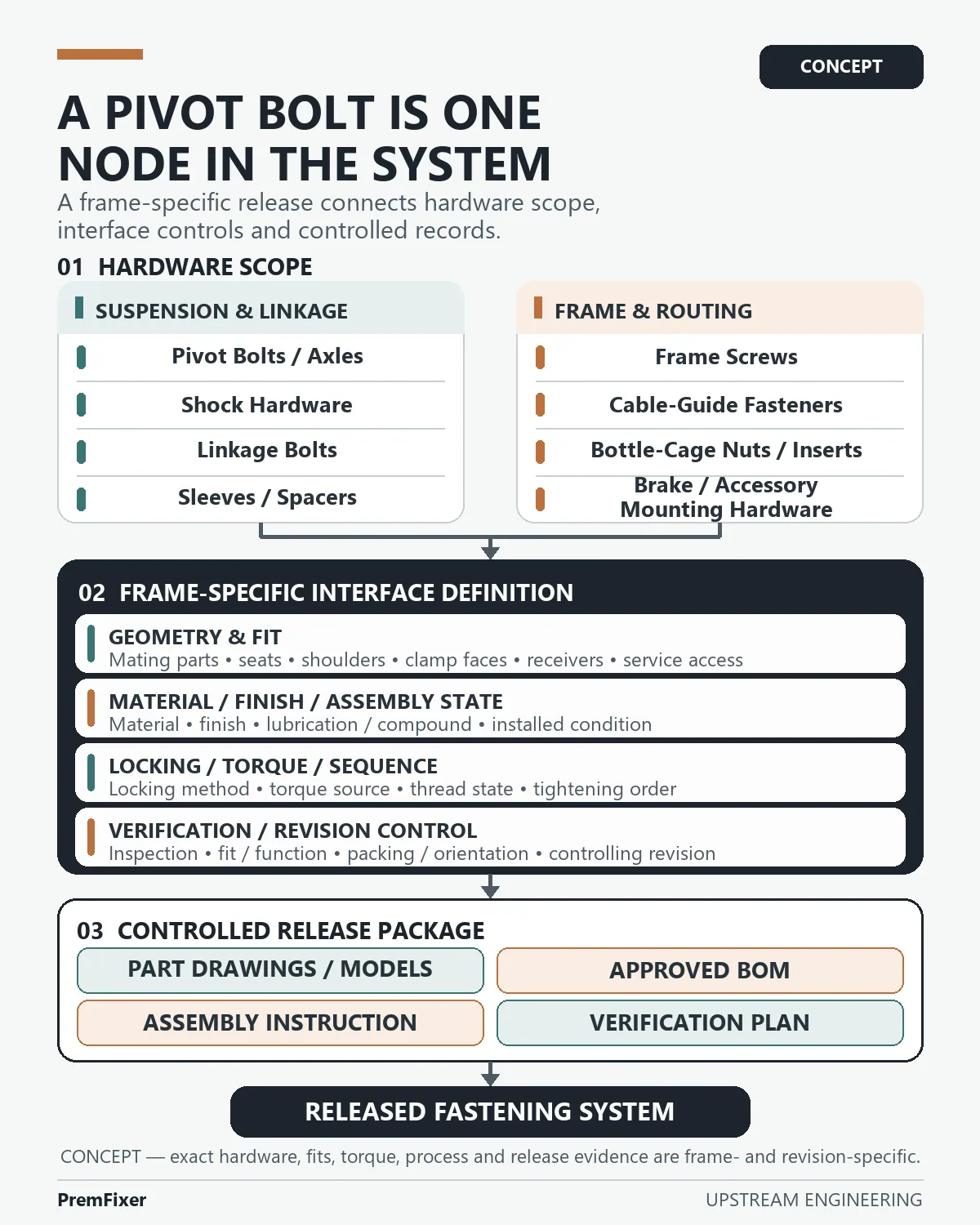
A full-suspension frame can contain pivot bolts and axles, shock hardware, linkage bolts, sleeves and spacers, frame screws, cable-guide fasteners, bottle-cage nuts or inserts, and brake or accessory mounting hardware.
Putting those line items into one BOM does not yet make them a fastening system.
The system emerges when each item is connected to a mating interface, an assembly condition, a governing revision and an acceptance decision. A bolt drawing may define the bolt. It cannot, by itself, define the bearing seats around it, the support span through the joint, the receiver it engages, the shock configuration beside it or the installation process that creates the intended clamp state.
This leads to the article's central engineering inference:
A premium full-suspension fastening system is not a bag of better bolts; it is a revision-controlled set of joint interfaces, hardware, assembly instructions and verification requirements.
That sentence is an engineering argument, not a quotation from a manufacturer and not a measured PremFixer result. The exact system remains specific to the frame platform, size, model year, joint design and released documentation.
1. Start with the interface map, not the fastener list
An isolated part number answers a narrow question: which component is being purchased?
The joint interface has to answer more:
- Which fixed and moving members meet at this location?
- Are bearings or bushings present, and how are their inner and outer members supported?
- What establishes the support span and lateral position?
- Which shoulder, sleeve, spacer, washer, clamp face or configuration part belongs in the stack?
- Where do the threads engage, and from which side must the joint be serviced?
- Which frame and shock revision controls the answer?
These are not cosmetic details around the fastener. They define what the fastener is being asked to do.
Official architecture descriptions help show why the map matters. Giant describes Maestro as four pivot points and two linkages working together.[1][2] Specialized describes FSR as a four-bar linkage whose operation depends on the placement of linkages, pivots and the rear axle.[3] Those descriptions belong to their respective systems; they are not interchangeable templates. Their value here is narrower: a suspension frame is a connected mechanism, so a fastener location cannot be separated from the members and axes that it connects.
For a real program, the first useful deliverable is therefore a frame-interface map tied to the governing configuration. The map does not replace detailed drawings. It tells every drawing and BOM line where it belongs.
2. Shock mounting exposes the “one universal bolt” problem
The shock interface is a clear example of configuration dependence.
Giant's current dual-suspension manual contains frame- and model-year-specific shock mounting configurations.[2] RockShox distinguishes standard eyelet hardware with spacers, bearing-eyelet arrangements and trunnion configurations, and directs the user to the frame manufacturer for compatibility and required mount-hardware sizes.[5]
The safe conclusion is not that one arrangement is better. It is that “shock bolt” is an incomplete sourcing description.
Before hardware release, the project must identify the actual eyelet or trunnion arrangement, the mating frame or link features, the required sleeves or spacers, the receiver, service direction and authoritative assembly requirements. If the frame or shock specification changes, the mount hardware cannot remain on an assumed revision.
This same logic applies to pivot hardware. “Main pivot axle” names a location, but not the complete support and clamp stack at that location.
3. Treat every pivot as a controlled stack
A pivot stack may contain an axle or bolt, opposed bearing inner races or bushings, one or more sleeves/spacers, link or frame faces and a threaded receiver or nut. The exact architecture varies, so no universal stack is proposed here.
The engineering review should still ask the same type of questions:
Support
Which surfaces carry and locate the inner members? Does the shoulder or sleeve support the intended span, or does a thread or relief enter a region where the design expected support?
Alignment and fit
Are opposed bearing seats and the axle path defined from functional datums where the design requires alignment? SKF's general rolling-bearing guidance makes fit selection dependent on the actual ring/load and seat conditions and warns that standard recommendations do not cover every application detail.[8] This is a reason to analyse the real bicycle joint, not a prescription for one tolerance class.
ASME Y14.5 provides a common language for communicating form, fit, function and interchangeability through drawings and model data.[6] The applicable datum scheme and geometric controls must still come from the design intent and governing documentation. A drawing is not improved by adding controls that have no defined functional relationship.
Clamp and retention
Where is the clamp load intended to pass? What receiver is engaged? Which elements rotate, and which are intended to remain clamped? What locking method and service access are compatible with that arrangement?
When those questions are unanswered, specifying the bolt more precisely may still leave the joint ambiguous.
4. Installation state connects finish, lubrication, locking and torque
Finish is often discussed as if it were a colour selection. In a threaded joint, its engineering boundary can be broader.
Within its scope for electroplated fasteners, ISO 4042 addresses dimensional requirements and coating systems that may include sealants, top coats or lubricants, together with assembly and material-risk considerations.[7] It does not select a coating for a bicycle frame and does not establish corrosion performance for a proposed part without a governing specification and evidence.
The practical implication is that base material, finish, lubricant or threadlocker, locking method, torque source and sequence should be reviewed as one installation condition. Changing one element can change the assumptions behind another.
Torque deserves particular discipline. NASA's fastener references discuss material, plating, lubrication, locking methods, thread classes, loads, grip and torque as interacting variables.[9] A separate NASA methodology treats the torque/preload relationship statistically and accounts for prevailing torque.[10] These are aerospace references, not bicycle acceptance procedures. Their appropriate use here is the general caution: torque is an indirect control used to create preload under defined conditions. It is not an intrinsic property of a bolt SKU.
Therefore, a complete system definition should identify the authoritative source for torque and the installation state to which it applies. Publishing a generic torque table without the joint, thread, under-head, lubrication, locking and sequence context would create false certainty.
5. A frame-level fastening map contains different hardware families
The suspension pivots are only one part of the frame system. For today's conceptual map, the hardware families are grouped as follows.
Suspension and linkage
- Pivot bolts and axles connect major rotating interfaces and require a defined support, receiver and service path.
- Shock hardware must match the actual frame/shock mounting arrangement.
- Linkage bolts belong to real link axes and released link orientations.
- Sleeves and spacers establish support, separation or stack position as defined by the joint.
Frame and routing
- Frame screws may retain covers, guards or other frame features according to the actual design.
- Cable-guide fasteners belong to a routing interface whose location and receiver must be defined.
- Bottle-cage nuts or inserts create a threaded interface in the frame and must be treated as part of that local construction.
- Brake and accessory mounting hardware belongs to the relevant mounting interface and governing component/frame requirements.
This grouping is not a claim that every bike uses every family, or that one generic set is compatible across models. It is a way to prevent smaller frame fasteners from being excluded when the project defines “the fastening system.”
When a sourcing team uses the phrase Complete Fastener Kit, the kit should be the output of a controlled interface definition—not a shortcut around it. CNC Manufacturing can execute a released component geometry; it cannot resolve an undefined mating stack, receiver, installation state or verification requirement.
It also changes the purchasing conversation. Instead of asking only whether the supplier can quote each line, the project can ask whether the inputs define each line's mating interface and acceptance boundary.
6. The documents must describe the same system
A useful system definition connects several controlled records. The exact document set is project-specific, but the following structure is a practical engineering inference from the source material:
- Pivot and fastening-interface map Links every hardware location to the frame platform, size, model year and revision.
- Approved BOM Identifies the required hardware and configuration parts without becoming the only source of geometry or assembly intent.
- Part drawings or models Communicate the controlled component features, datums and requirements needed for fit and function.
- Assembly instruction Carries orientation, stack order, approved installation products, torque source, sequence, service direction and functional checks as applicable.
- Verification plan Defines what part, fit, alignment, assembly and movement evidence closes each interface before release.
Pivot's current frame-bearing service manual is useful context because it addresses bearings, links, pivot and shock hardware, spacers or configuration parts, assembly products, ordered assembly and movement checks within one service procedure.[4] Those details are Pivot-specific and must not be copied into another frame. The broader lesson is the scope: the serviceable assembly is controlled through relationships among parts, products, sequence and checks.
When one record changes, change control should ask what else becomes stale. A revised shock configuration may affect mount hardware and spacers. A revised bearing or finish may affect fit, assembly products or inspection. A revised frame feature may affect service access or receiver engagement.
The release object is therefore not a static spreadsheet. It is the agreement among the records that define each physical interface.
7. Evidence should close interfaces, not decorate the RFQ
“Premium” is not established by naming an alloy, a coating or a low-mass target. In this context, a better working definition is controlled requirements with evidence appropriate to the joint.
Before a fastening-system release, the cross-functional team can ask:
- Which frame platform, size, model year and drawing/BOM revision define the interface map?
- Which mating parts, bearing or bushing type, support span, clamp faces and receivers belong to each joint?
- Which characteristics live in the part drawing, and which belong in the BOM or assembly instruction?
- Where functional relationships require it, which datums and geometric controls communicate alignment and fit intent?
- Which base material, finish, lubricant, retaining compound or threadlocker is approved for the actual mating materials and environment?
- What is the authoritative source for torque, installation condition and sequence?
- Which joints require prototype fit review, first-article inspection or a functional movement check?
- How are left/right, upper/lower, spacer orientation and revision protected in packing and line-side information?
- Which records must accompany release, and which questions stay open until those records exist?
These questions do not guarantee an outcome. They make the unknowns and decision owners visible before the hardware is treated as complete.
8. Where PremFixer can enter the conversation
PremFixer's current website provides a bounded starting point: an RFQ can begin from a drawing, sample or OEM BOM, and the review can include mating-interface, assembly, fit, finish, inspection and packing requirements.[11][12][13]
That is the approved company context for this article.
It is not evidence that PremFixer has delivered a particular complete frame-level kit, owns a customer's coordinated BOM, guarantees compatibility or has achieved a specific quality, lead-time, field-life or performance result. Those claims would require separate, project-specific records.
For a real RFQ, the most useful next step is to send the controlled input and identify the interface questions that remain open. A drawing defines more when it travels with the frame location, mating stack, assembly condition and verification requirement it is meant to support.
Conclusion
A premium full-suspension fastening system begins before the purchase order and before the parts are packed.
It begins when engineering, product, quality, assembly and purchasing agree on the physical interfaces: what connects, what supports, what clamps, what rotates, what receives the thread, how the joint is installed and what evidence releases it.
The bolt still matters. So do the axle, bearings, sleeves, spacers, shock hardware, frame inserts and smaller routing or accessory fasteners around it.
The system is the controlled relationship among them.
Author & Contact
Kang Wang
PremFixer
https://premfixercnc.com/
References
All links were verified by Research on 2026-08-15.
- Giant Bicycles, Maestro Full Suspension Mountain Bike Technology.
- Giant Group, Dual Suspension User Manual, dated 2025.12.
- Specialized Bicycle Components, FSR Suspension Technology.
- Pivot Cycles, 2025 Frame Bearing Service.
- SRAM–RockShox, Suspension User Manual.
- ASME, Y14.5-2018 (R2024), Dimensioning and Tolerancing.
- ISO, ISO 4042:2022, Fasteners — Electroplated coating systems.
- SKF, Rolling Bearings, publication 17000 EN.
- NASA, Fastener Design Manual, Reference Publication 1228.
- NASA Marshall Space Flight Center, Methodology for Determining Limit Torques for Threaded Fasteners.
- PremFixer, Custom Bicycle Fastener Manufacturer.
- PremFixer, Bicycle Fastener Catalog & Drawing-Led Product Index.
- PremFixer, PS-P Axle Cores.
Claim-to-Source Map
| Claim ID | Type | Article claim | Evidence | Boundary |
|---|---|---|---|---|
| C1 | Source fact | Giant describes Maestro as four pivots and two links working together. | References 1–2 | Giant-specific architecture description only. |
| C2 | Source fact | Official Giant model tables show shock-mount configuration and hardware variation across frames/model years. | Reference 2 | Examples only; no values are transferred. |
| C3 | Source fact | Pivot's service manual addresses links, bearings, pivot/shock hardware, spacers/configuration parts, assembly products, sequence and movement checks in one procedure. | Reference 4 | Pivot-specific; not a universal assembly instruction. |
| C4 | Source fact | RockShox distinguishes standard eyelet/spacer, bearing-eyelet and trunnion arrangements and defers compatibility/size to the frame manufacturer. | Reference 5 | Applies to covered products only. |
| C5 | Source fact | ASME Y14.5 is a language for communicating form, fit, function and interchangeability. | Reference 6 | Compliance only when invoked by governing documentation. |
| C6 | Source fact | ISO 4042 treats electroplated-fastener coating systems as having dimensional, lubricant, assembly and material-risk considerations within its scope. | Reference 7 | No coating selection or performance claim. |
| C7 | Source fact | SKF fit guidance depends on actual ring/load and seat conditions. | Reference 8 | General bearing engineering, not a bicycle fit prescription. |
| C8 | Source fact | NASA's torque methodology treats torque/preload and prevailing torque statistically. | Reference 10 | Aerospace context; no bicycle value or procedure is transferred. |
| C9 | Company context | PremFixer's current site accepts drawing/sample/OEM-BOM RFQ inputs and presents suspension/pivot hardware routes. | References 11–13 | No complete-kit delivery, compatibility or result claim. |
| I1 | Engineering inference | The procurement object should be the joint interface and controlled stack, not the isolated bolt alone. | C2–C8 collectively | Framed explicitly as an engineering inference. |
| I2 | Engineering inference | The interface map, BOM, drawings/models, assembly instruction and verification plan should agree. | References 2, 4–6, 9 | Exact document set is project-specific. |
| I3 | Engineering inference | Finish, lubrication/threadlocker, locking, torque and sequence should be reviewed as one installation condition. | References 4, 7, 9–10 | No quantitative relationship without project data. |
| I4 | Engineering inference | Bearing seats, axle shoulders, sleeves/spacers, clamp faces and receivers should be reviewed as one fit/alignment chain. | References 4, 6, 8 | No invented dimension, tolerance or datum scheme. |
| I5 | Engineering inference | “Premium” should mean controlled requirements and evidence, not a named material, finish or mass target by itself. | References 6–9 | Editorial framing, not a measured market definition. |
Suggested Hashtags
#BicycleEngineering #FullSuspension #BicycleFasteners #FrameHardware #CompleteFastenerKit #CNCManufacturing #PivotHardware #ShockHardware #FastenerEngineering #BicycleOEM #SupplierQuality #PremFixer
Start With the Actual Interface
Send the drawing or sample and the application context so the discussion stays tied to the approved part and its joint.
Send a Drawing or Sample