

“Control the pivot-bolt concentricity to ±0.01 mm.”
It sounds like a strong requirement. It has a small number, an engineering term and an implied quality threshold. Yet a supplier cannot manufacture or inspect it consistently until several more questions are answered.
Concentric to what datum? Which cylindrical feature is controlled? Does the function depend on the axis location, the variation during rotation, the surface form, the bearing fit, or a combination of those characteristics? What happens when the joint is clamped? How will the datum be simulated during inspection?
This does not mean alignment is unimportant. It means that the tolerance value cannot be separated from the joint.
For a full-suspension MTB or a bearing-supported gravel-frame pivot, the useful engineering objective is to maintain the intended bearing-seat and pivot-axis relationship through manufacturing, assembly and service loading. The path to that objective is not a magic number. It is a chain:
function → datum → geometric controls → fit → process → measurement → capability → assembly validation
1. Start with the physical joint
A linkage pivot normally contains more than a bolt and one bearing. A simplified stack may include two frame or linkage supports, two bearing inner races, a continuous through-spacer, a smooth pivot shoulder, head and receiver interfaces, seals and clamp faces.
Each feature has a different job:
- The bearing seats in the frame or linkage position the outer rings.
- The inner races and through-spacer form a clamp stack.
- The smooth shoulder locates or supports the stack, depending on the architecture.
- The head and receiver close the joint.
- The frame and linkage structure control how the two sides remain aligned under clamp and external load.
If the design team controls only the diameter of the bolt shoulder, it has not controlled the complete axis relationship. If it controls only the bolt axis but allows the two bearing bores to point in different directions, the assembled bearing rings can still be misaligned. If it specifies a tight fit without considering internal clearance and assembly, it can create a different problem.
The CTQ must therefore come from the functional stack, not from a copied supplier capability line.
2. “Concentricity” may not be the characteristic you need
ISO 1101 defines the symbol language and rules for geometrical specifications covering form, orientation, location and runout. ASME Y14.5 provides another widely used GD&T framework, with datum-reference, position, profile, axis and runout tools. The drawing should state its governing system and edition rather than mixing conventions.
For a pivot shoulder and bearing stack, several controls may be relevant.
Size
The shoulder diameter and bearing bore relationship contributes to the fit. Size alone does not limit roundness, straightness of the derived axis or variation relative to another datum unless the selected specification system and controls explicitly do so.
Roundness and cylindricity
These are form questions. They ask whether the individual seat surface has the required shape. They do not, by themselves, locate that surface relative to a functional datum axis elsewhere on the part or assembly.
Position or coaxial relationship
If the purpose is to locate a cylindrical feature’s derived axis relative to a datum reference frame, a location control may communicate the functional requirement more directly. The feature, datum sequence, modifiers and interpretation still have to be defined.
Circular runout and total runout
Runout evaluates surface variation as the part rotates about a datum axis. It can combine the effects of location, orientation and form that appear during rotation. Circular and total runout are not interchangeable: one evaluates individual circular elements, while the other considers variation across a surface over the scan.
Surface texture
Roughness is another characteristic, not a substitute for size or form. A value such as Ra 0.4 may be appropriate for a particular qualified seat, but it is not an automatic rule for every bicycle pivot bolt. The correct texture depends on the mating surface, fit, material, coating, lubrication, process and bearing-maker guidance.
The release drawing may need more than one of these controls. The goal is not to maximize the number of symbols. It is to state the minimum complete set that protects function and can be measured economically.
3. Axis error changes the contact path
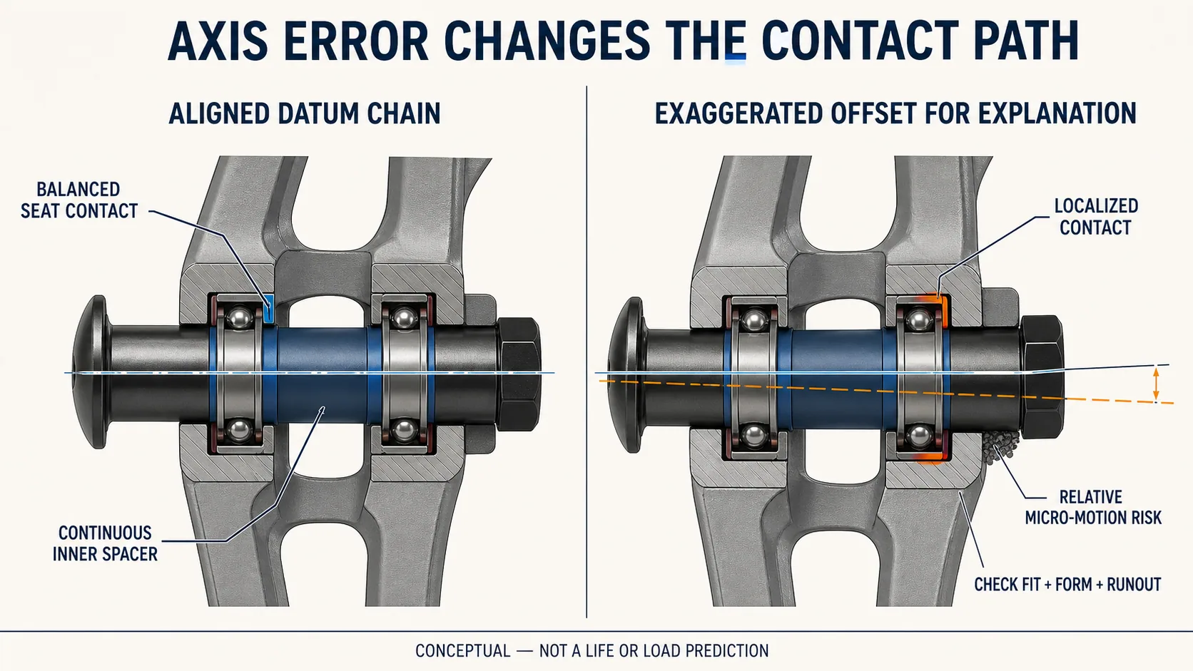
When the bearing inner and outer rings are angularly misaligned, load distribution can become less uniform. Bearing manufacturers discuss misalignment, shaft/housing deflection and seat accuracy because those conditions can move contact toward an edge or otherwise alter the loaded zone.
That general mechanism is relevant to a bicycle linkage, but it does not justify an invented service-life percentage. The magnitude depends on bearing type, internal geometry, clearance, load, oscillation, support stiffness and lubrication.
A second mechanism is relative movement at a ring/seat interface. SKF’s bearing-damage guidance describes fretting corrosion as arising from micromovements between mating surfaces such as a bearing ring and its shaft or housing seat. Too-loose fits and form inaccuracies are among the possible contributors. Oxidized debris and continued movement can worsen the seat condition and disturb support.
This should not be simplified into “eccentric bolt equals broken bearing.” A pivot may show noise or wear for other reasons: incorrect preload, contaminated interfaces, spacer-length error, damaged seals, loose receivers, deformed supports or poor maintenance. Diagnosis requires evidence from the actual assembly.
The engineering conclusion is narrower and stronger: axis, form, fit and clamp state can change the contact path and relative movement, so they should be reviewed together.
4. There is no universal zero-clearance fit
The phrase “zero clearance” sounds desirable because it suggests rigidity. In a bearing arrangement, both excessive looseness and excessive interference can be harmful.
SKF guidance explains that a loose fit can permit relative movement, smearing, wear and fretting. The same guidance warns that an overly tight fit can reduce bearing internal clearance, increase operating temperature and, in severe cases, raise ring stress enough to contribute to fracture.
The correct fit depends on:
- which ring sees the rotating or indeterminate load;
- the magnitude and direction of the load;
- bearing type, size, tolerance class and internal clearance;
- shaft/seat and housing materials;
- wall thickness and stiffness of the linkage support;
- coating or finish build;
- temperature and assembly method;
- service and disassembly requirements.
For bicycle pivots, the inner race may be clamped against a spacer rather than rotating continuously on the pivot shoulder. The selected fit and clamp strategy must match that architecture. Do not import a high-speed rotating-shaft rule without checking the load and motion state.
ISO 492 specifies dimensional and geometrical characteristics for radial-bearing interfaces, while bearing manufacturers provide application guidance for seats and fits. Neither source gives one universal ±0.01 mm shoulder requirement for every bicycle pivot.
5. The process route follows the datum strategy
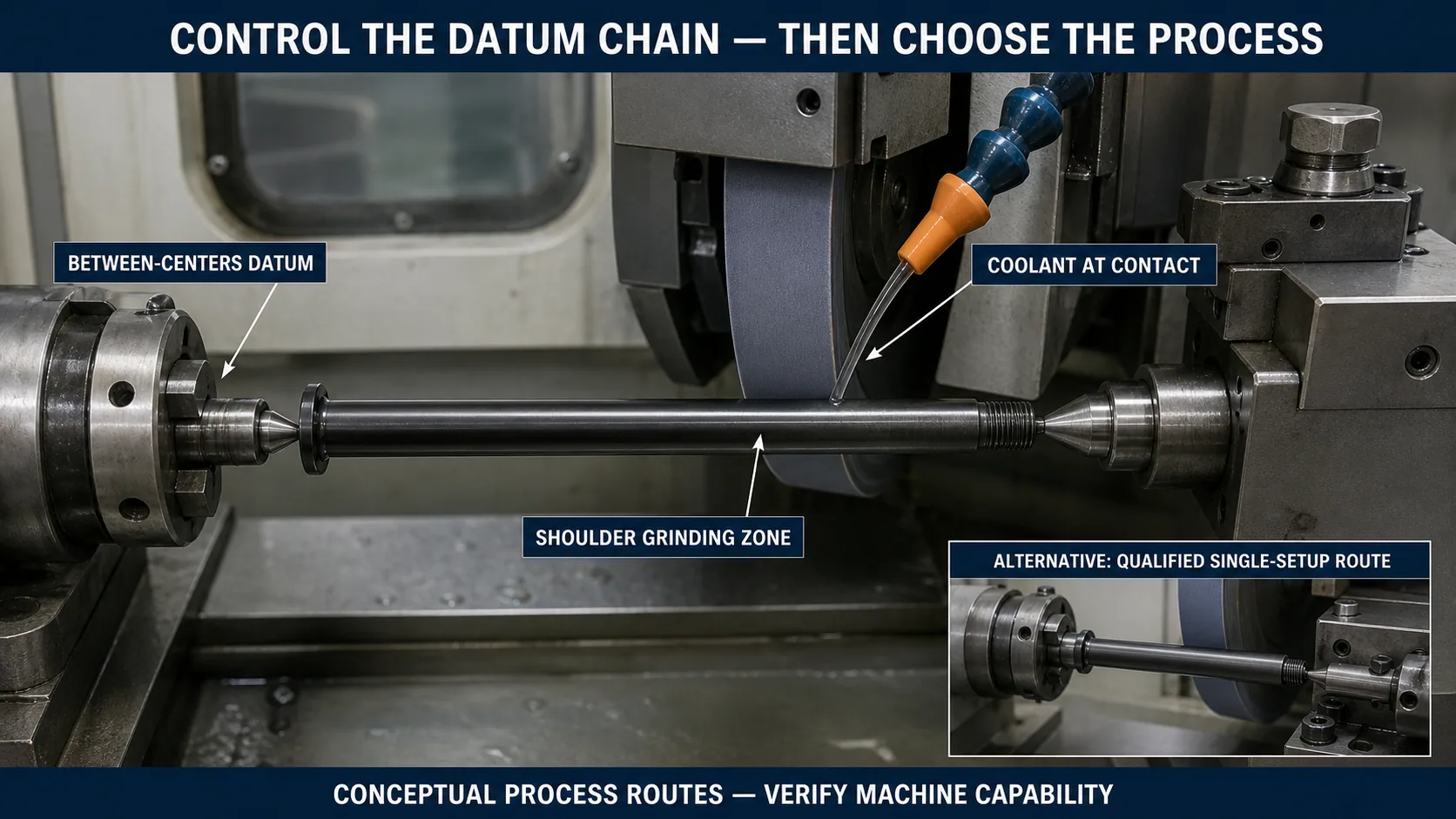
The original draft claimed that ordinary turning cannot meet the required geometry and that CNC turn-mill plus cylindrical grinding is the necessary solution. That conclusion is too broad.
Cylindrical grinding can be a strong route when the design needs a controlled bearing shoulder relative to centre features or another qualified datum, particularly when material condition, surface texture or process capability makes grinding useful. Between-centres processing can also preserve a repeatable axis across operations when the centre features and handling are controlled.
But grinding is not proof by itself. Centre-hole condition, support stiffness, wheel condition, thermal control, coolant delivery, dressing, stock allowance and inspection all influence the result. Moving the part between machines can introduce a datum-transfer error if the process plan does not preserve the functional axis.
A qualified single-setup turning or turn-mill route may also meet the drawing when machine condition, tooling, workholding, thermal behaviour and measurement evidence support it. Other specialized finishing routes may be viable as well.
The supplier should propose the simplest capable route and show evidence against the actual characteristic. The drawing should not prescribe an additional operation merely because its name sounds more precise.
A practical process review asks:
- Which physical feature establishes the functional datum at each operation?
- Which CTQs are completed in the same setup?
- Where is the part re-clamped, and what error can that transfer introduce?
- How are heat, tool/wheel condition and material state controlled?
- How will the final inspection reproduce the drawing datum?
6. Match the inspection method to the measurand
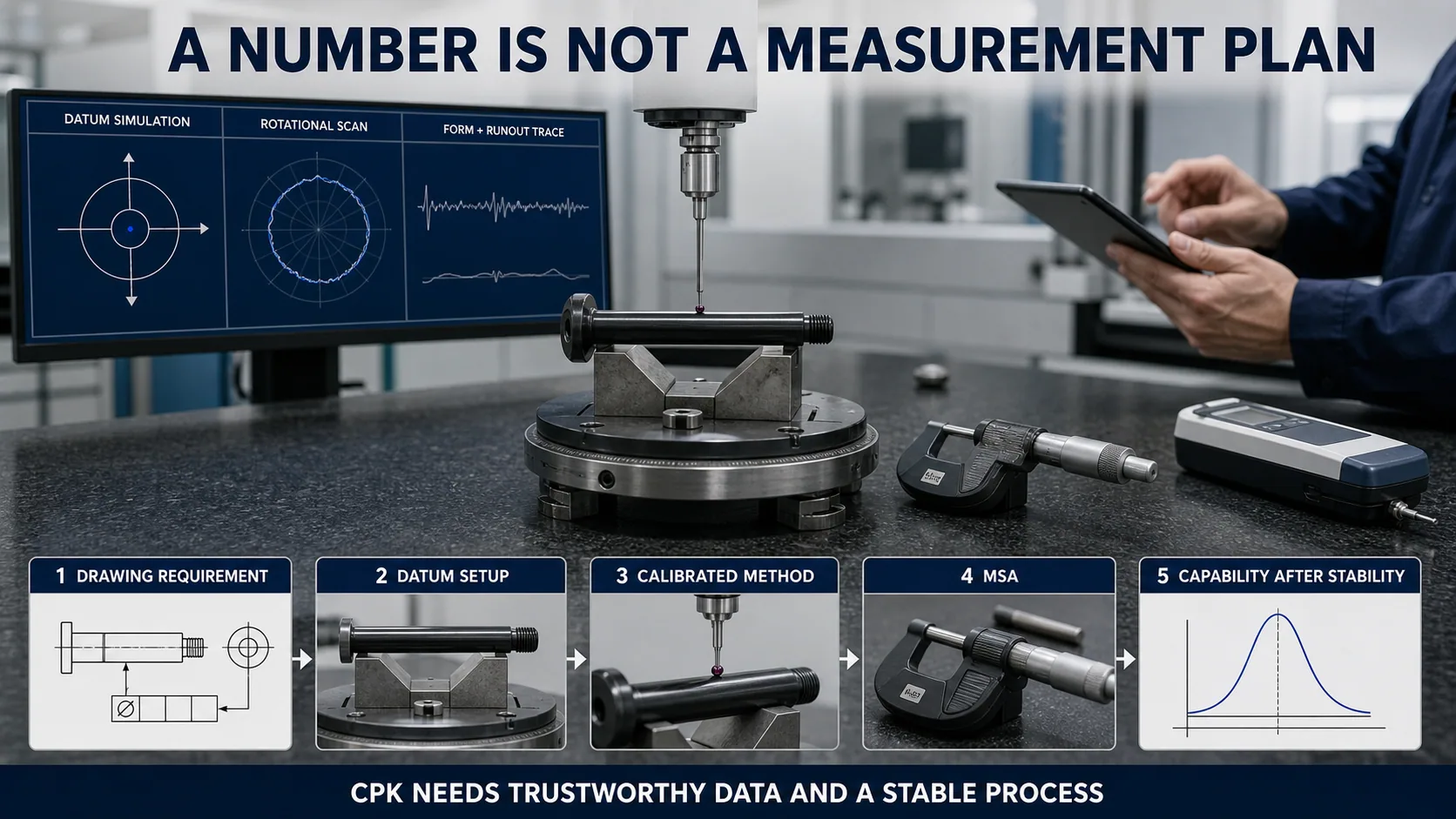
An optical comparator is useful for many silhouette and profile measurements. It should not automatically become the acceptance method for a three-dimensional datum-referenced shoulder-axis or runout requirement.
Depending on the controlled characteristic, a suitable method may use:
- a calibrated diameter instrument for size;
- a roundness/cylindricity system with a defined rotational datum;
- a dial or electronic indicator on a qualified fixture for runout;
- a CMM with an adequate probing strategy and evaluated datum simulation;
- a surface-texture instrument for the stated texture parameter;
- a functional gauge when the specification and decision rule support one.
The inspection plan should define the fixture, datum simulation, contact points or scan paths, sampling/filtering, environmental condition, equipment resolution and calibration status. It should also address measurement uncertainty relative to the tolerance and the risk of false acceptance or rejection.
NIST’s guidance makes the principle clear: metrology capability must be considered before the study, and measurement devices should remain under quality control during the work. Instrument resolution alone is not proof that the measurement process is capable.
7. Cpk is the end of the evidence chain, not the beginning
Cpk compares the location and variation of a process with specification limits. It can be useful, but only when its prerequisites are credible.
Before requesting a Cpk report, confirm:
- the specification is unambiguous and function-based;
- the measurement system is suitable and stable;
- the process is in statistical control;
- sampling is independent and representative;
- the distribution model is appropriate, or an alternative method is justified;
- sample size and confidence are adequate for the decision;
- subgrouping, cavities, machines, tools, shifts and lots are not being hidden in one summary number.
NIST notes that conventional capability indices compare a stable process with its specification limits and that normality and sample-size considerations affect interpretation. It also explains that Cpk accounts for the process being off-centre, unlike Cp.
The supplier evidence pack should therefore include more than a Cpk headline: measurement-system evidence, control-chart history, raw-data traceability, sampling logic, distribution review and the exact drawing revision.
8. A release-ready CTQ package
For a bearing-supported bicycle pivot, the design and quality teams can align around eight deliverables:
- Assembly section: bearings, spacer, bolt shoulder, head, receiver, seals and clamp faces.
- Functional datum structure: the feature or feature pattern that establishes the pivot axis.
- Feature controls: size, form, position/runout, shoulder orientation and texture where function requires them.
- Fit and stack definition: finished-condition dimensions, coating allowance, internal-clearance effects and spacer length.
- Process plan: setups, datum transfers, stock/finish sequence and CTQ control points.
- Inspection plan: method, fixture, datum simulation, scan path, environment, calibration and uncertainty.
- Process evidence: MSA, stability, capability and lot traceability.
- Assembly validation: clamp state, articulation, noise/play checks and test evidence appropriate to the frame program.
This package does not guarantee a bicycle’s service life. It makes the engineering decisions visible, testable and auditable.
Conclusion
A ±0.01 mm target may eventually be the correct result for a defined pivot feature. It may also be unnecessarily tight, attached to the wrong characteristic or impossible to verify with the proposed method.
The number becomes meaningful only after the team defines the functional datum, bearing and spacer stack, fit, form, runout relationship, manufacturing route and measurement decision.
For frame engineers, the question is not “How small can we make the tolerance?”
For quality directors, it is not “Does the supplier have a Cpk report?”
The shared question is: Can we trace the CTQ from the joint’s function to a repeatable measurement and a stable process?
That is the foundation for a pivot system whose alignment claims can survive a design review, supplier audit and assembly trial.
Author & Contact
Kang Wang
Senior Product & Technical Lead | Bicycle & Motorcycle Division
PremFixer (Guangdong Pinshang Hardware Co., Ltd.)
Website: https://premfixercnc.com/
WhatsApp: +86 15766506531
References
- ISO 1101:2017 — Geometrical product specifications: geometrical tolerancing
- ASME Y14.5-2018 (R2024) — Dimensioning and Tolerancing
- ISO 492:2023 — Radial bearings: GPS and tolerance values
- SKF Bearing Maintenance Handbook
- SKF — Bearing damage analysis and ISO 15243
- Schaeffler — Technical Principles: bearing seating surfaces
- NIST — Assessing Process Capability
- NIST — What is Process Capability?
- NIST — Is the Measurement System Capable?
Claim-to-Source Map
| Claim used | Source | Boundary |
|---|---|---|
| Form, orientation, location and runout require defined geometrical specifications | ISO 1101; ASME Y14.5 | Standards frameworks; drawing must state the governing system/edition |
| Radial-bearing interfaces have dimensional and geometrical characteristics | ISO 492:2023 | Does not prescribe one MTB pivot-bolt tolerance |
| Loose fits/form errors can contribute to relative movement and fretting; excessive interference can also damage bearing behaviour | SKF maintenance/damage guidance | General bearing mechanism; not a diagnosis or life prediction for a specific bicycle |
| Multiple bearing seats and shoulders need form/runout/coaxial review | SKF and Schaeffler bearing-seat guidance | Application value must follow actual bearing arrangement |
| Cpk compares a stable process with specification limits and has sampling/distribution prerequisites | NIST Engineering Statistics Handbook | No universal Cpk acceptance value is asserted here |
| Grinding and single-setup processing are candidate routes | Engineering inference from datum-transfer principles | Conceptual only; no PremFixer machine-capability claim |
Suggested Hashtags
#BicycleEngineering #FrameDesign #PivotHardware #GDandT #GeometricTolerancing #QualityAssurance #Metrology #BearingFit #SupplierQuality #PrecisionMachining #PremFixer
Start With the Actual Interface
Send the drawing or sample and the application context so the discussion stays tied to the approved part and its joint.
Send a Drawing or Sample