
A scratch on a 7075 pivot does not prove that the cutting tool has built-up edge. Built-up edge concerns workpiece material adhering to the cutting edge; a component mark can also arise from other cutting, chip-contact, workholding or later handling conditions. For an OEM reviewing a surface complaint, identify the affected region and the first stage where the mark is present. Then compare the actual tool and process evidence with that observation. Select a response for the supported mechanism and verify the required final feature. A photograph alone does not establish a tool diagnosis, a roughness value or a universal instruction to increase cutting speed.
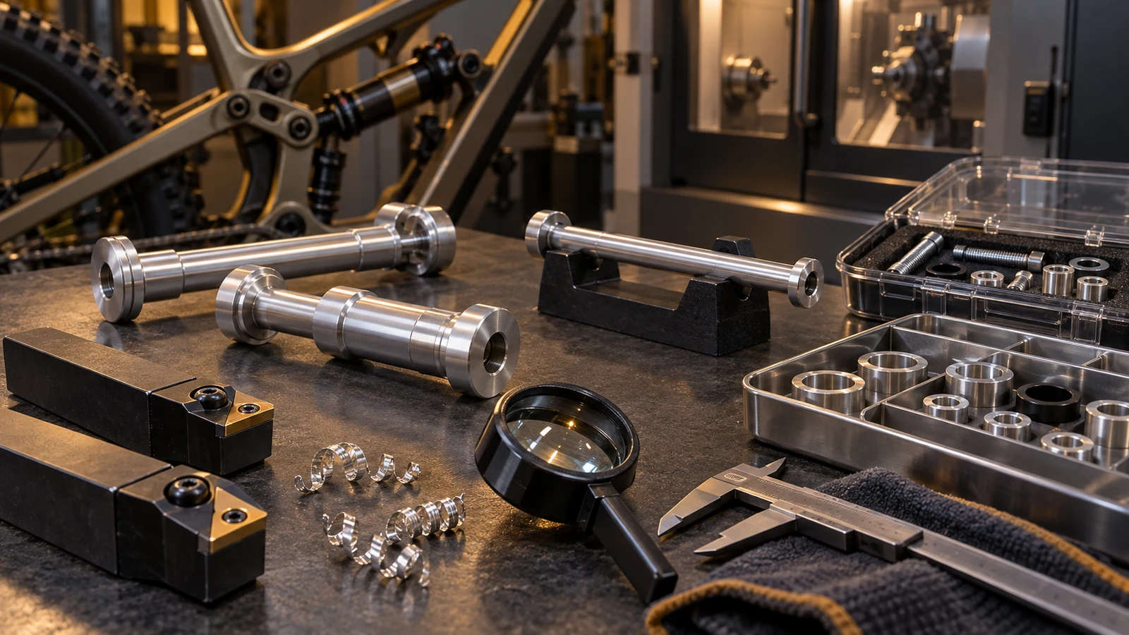
Hero: concept illustration of example hardware and its application. It is not a factory photograph, tested component or approved production geometry.
Built-up edge is a tool mechanism, not a surface label
Seco's tool-wear guide describes built-up edge as adhered workpiece material at the cutting edge and explains that detachment can damage the edge. That mechanism requires relevant tool evidence, not merely a photograph of a finished axle.
Identify the cutting edge and operation that produced the region under review. Retain the observed condition of that edge with the corresponding output. A shiny deposit can support investigation, but the project still needs to establish what was observed and whether it relates to the component concern.
Do not describe a generic concept image as an actual tool micrograph. Nor should a tool-wear description be converted into a fixed surface result for 7075. No measured PremFixer tool condition, adhesion event or roughness capability is supplied here.
Locate the first observed stage before changing the cut
As engineering analysis, compare the same affected region at relevant stages: after cutting, after removal from the fixture, after transfer and after any later processing. Record which states were actually observed. A missing earlier observation is an uncertainty, not evidence that the mark was absent then.
If the region was documented without the mark before transfer and with it afterward, the handling path becomes relevant. If it was already present at the cutting stage, review that operation and tool. Neither observation alone identifies every mechanism, but they support different next investigations.
The workholding-mark guide addresses contact between the support arrangement and protected features. Keep that interface question distinct from cutting-edge adhesion. Changing cutting speed cannot be assumed to correct a mark created elsewhere in the route.
| Observation | Useful investigation | Unsupported shortcut | Verification connection |
|---|---|---|---|
| Relevant edge adhesion | Represented tool and cutting operation | Every component scratch called built-up edge | Affected part feature and comparable output |
| Mark at a cutting-stage observation | Tool, chip and active setup | Appearance treated as unique cause proof | Specific hypothesis and process evidence |
| Mark first documented after transfer | Contact and handling path | Cutting speed changed without stage evidence | Comparable before/after states and feature assessment |
| Average texture result | Specified profile under its conditions | Local scratch automatically accepted | Named region and separate local-defect disposition |
| Polishing or later finish proposal | Retained geometry and supplied surface | Brighter appearance called a corrected part | Required dimensions and final surface acceptance |
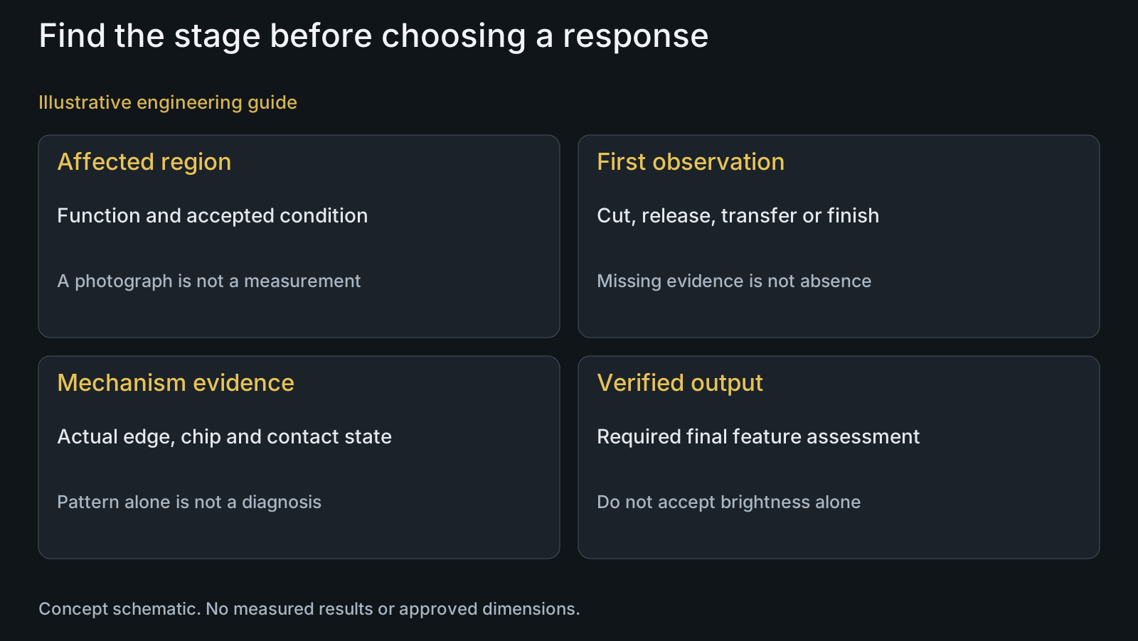
Compare tool, chip and contact evidence without naming a cause too early
Record the active tool, represented cut and available chip observations. Identify whether a change occurred in the tool, support, fluid delivery or transfer method. Comparing different states without retaining those changes makes the diagnosis less specific.
A visible surface pattern can guide where to inspect, but it is not a unique fingerprint of one cause. Chip contact, a support interface and a tool-related disturbance are different hypotheses. Ask what evidence would distinguish them instead of calling every longitudinal mark a built-up-edge scratch.
The coolant-condition guide addresses fluid interpretation separately. An acceptable concentration value does not prove every delivery or tool condition, and a changed coolant record does not independently diagnose the marked part.
A machining response must match the supported mechanism
Seco lists cutting-condition, edge-geometry and coolant-related considerations for built-up edge. Those are mechanism-specific review inputs, not a machine-ready 7075 pivot recipe. Confirm the actual tool guidance and permitted setup before selecting a change.
Do not increase speed merely because a mark looks like a scratch. If the evidence points to transfer contact, the relevant response addresses that path. If cutting-edge adhesion is supported, compare an appropriate machining change while keeping the feature and supplied requirement fixed.
The 7075 high-speed machining guide addresses efficiency boundaries, not diagnosis of every surface concern. A faster cutting proposal must still deliver the required geometry and surface; neither speed nor a brighter appearance proves that requirement.
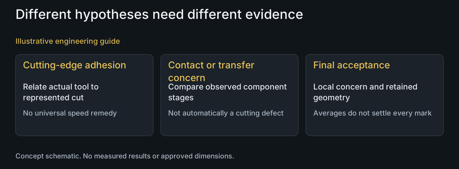
Verify the affected feature instead of hiding its appearance
Identify whether the mark concerns a locating surface, contact region or appearance-only area. Define the applicable acceptance task before choosing polishing or a later finish. A cosmetic action can change more than visibility when it removes material from a functional feature.
A surface photograph cannot supply a numerical Ra, scratch depth or dimensional acceptance. KEYENCE's profile-parameter explanation also distinguishes average texture from local defects. A compliant average measured elsewhere does not resolve the local concern.
If the route is changed, assess the relevant delivered region and dimensions under the agreed method. Later anodizing or coating does not automatically dispose of an unexplained substrate mark. Keep appearance review, local defect disposition and the specified texture check as distinct conclusions.
A transfer-stage observation changes the next investigation
Illustrative engineering example: assume a 7075 axle's locating region is documented after machining and again after transfer to a shared tray. A visible mark is present only in the latter observation, and no actual dimensional or texture measurements are supplied.
The review investigates the represented transfer and contact path before attributing the mark to built-up edge. It identifies the affected feature's acceptance requirement and whether the available observations are comparable. A machining-speed change is not selected merely because the complaint concerns a machined part.
If the evidence instead showed the mark at the cutting stage with relevant edge adhesion, the investigation would be different. Neither scenario reports a proven cause, successful correction or accepted component. The example shows why stage evidence determines the useful next comparison.
Request a surface review with both part and process context
Send the drawing and STEP, 7075 stock condition, marked surface, available stage photographs, final finish and quantities to the CNC turning review. Include relevant tool or handling observations without presenting them as a completed root-cause finding.
Connect any proposed material-removing or later surface work to the surface-treatment scope. The roughness and fatigue guide addresses why surface metrics do not independently establish a life improvement.
PremFixer reviews the agreed manufacturing definition and supplied acceptance. A useful request names the feature and concern, not just mirror finish or scratch-free. No universal Ra target, successful machining recipe or company surface-quality result is claimed here.
Questions buyers need to confirm
Does every aluminium pivot scratch prove built-up edge?
No. Built-up edge is a cutting-edge adhesion mechanism. Locate the first observed stage and compare relevant tool, chip and contact evidence before assigning the cause.
Should cutting speed always be raised to remove marks?
No. Select a response for the supported mechanism and actual permitted setup. A mark caused during transfer is not automatically corrected by changing the cut.
Can a finished-part photo establish Ra or scratch depth?
No. It can identify a visible region, not those numerical characteristics. Define the appropriate measurement and local-defect assessment for the affected feature.
Does an acceptable average texture mean the scratch is acceptable?
Not automatically. The evaluated region and local concern may differ. Assess the named defect separately from the average texture result and retain its functional acceptance basis.
Can polishing or anodizing dispose of an unexplained mark?
Do not assume so. Review the affected geometry and supplied surface. A changed appearance is not proof that the original concern or final dimensional requirement has been resolved.
What should accompany a 7075 surface-mark request?
Send drawing, STEP, stock condition, marked region, stage photographs, finish and quantities. Include relevant tool and handling observations and the acceptance requirement without claiming an unproven diagnosis.
Technical references and scope
Seco: Tool wear patterns in machining. Complete relevant built-up-edge mechanism and response text read; broader wear guide also previously read. No generic speed,feed,coolant concentration recipe or proven7075result adopted.
KEYENCE: Surface-height parameters. Previously fully read relevant average-profile/local-defect explanation. No questionable standard identifier or numerical limit adopted.
Explore related component, material and sourcing decisions in the customer decision knowledge center. For a drawing review, use the Drawing/BOM RFQ path.
Review the source of the mark before changing the route
Send the drawing, STEP, stock condition, marked surface and comparable stage photographs, together with finish and quantities. PremFixer will review the manufacturing context and relevant feature checks without declaring every scratch a built-up-edge defect.
Discuss the drawing and BOM