
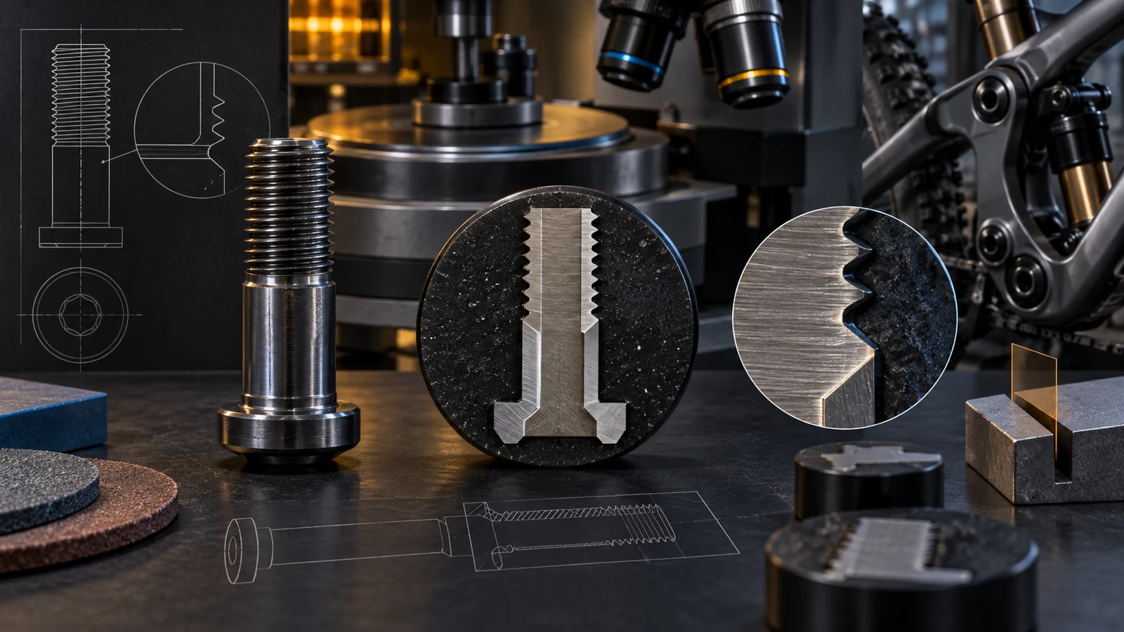
A pivot thread metallographic section can help examine a local root, flank, surface layer or suspected discontinuity, but it cannot show everything about the finished screw. OEM engineers should first identify the feature and the conclusion needed, then specify a section that actually intersects it. A longitudinal plane through the axis and a transverse slice expose different relationships; neither automatically represents every thread turn. The direct answer is to request location-specific, properly interpreted evidence alongside the relevant dimensional or mechanical checks. Do not approve fit, claim a manufacturing route or predict riding life solely from an attractive etched image.
Hero: concept illustration of example hardware and its application. It is not a factory photograph, tested component or approved production geometry.
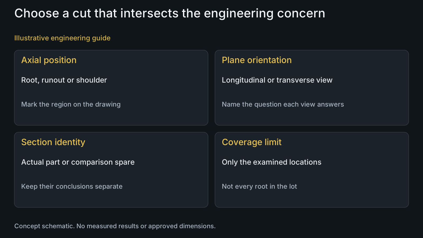
Choose the section plane from the suspected mechanism
Mark the cut direction on the drawing and identify the axial position relative to the shoulder, runout and full-form thread. A request for a thread cross-section without that map can produce a valid image of the wrong feature. Include the component's material condition and whether the concern arose before or after finishing.
A longitudinal section through the axis exposes a sequence of thread profiles in that plane. A transverse section addresses a particular axial position and circumferential view. An oblique cut changes the apparent profile. The laboratory should explain which plane is suitable for the question rather than treating these views as interchangeable measurements.
If the concern is confined to a marked region, preserve that location during selection and cutting. An unmarked spare may be suitable for a process comparison but cannot be described as the actual suspect part. The general pivot metallography guide addresses grain representation; this guide focuses on thread-feature coverage.
Keep the original thread edge visible
Struers identifies fastener clamping and mounting gaps around threads as preparation difficulties. Poor edge retention can obstruct coating examination. Ask the laboratory to document whether the critical root and outer surface survived preparation, especially when the engineering question is close to that edge.
Its preparation guidance also distinguishes scratches, smearing, edge rounding and pull-outs from the intended structure. A dark line or rounded boundary therefore needs interpretation, not automatic classification as a production defect. Preserve useful unetched observations before selecting an alloy-appropriate etching method.
Specify the overview and local images needed to locate an observation. A high-magnification crop with no component map leaves the buyer unable to distinguish root, crest, mounting boundary or cut edge. For a suspected discontinuity, ask what evidence supports its interpretation and what additional examination would resolve ambiguity.
| Decision | Useful evidence | Interpretation risk | Companion check |
|---|---|---|---|
| Local runout indication | Mapped cut intersecting the region | A remote clean section misses the concern | Location record and suitable further examination |
| Root or flank structure | Defined plane and local images | Oblique view mistaken for nominal profile | Section overview and orientation |
| Near-edge layer | Retained original boundary | Rounding or gaps obscure the edge | Preparation suitability and layer definition |
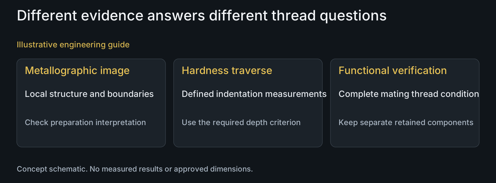
| Hardness-defined depth | Applicable hardness traverse | Visible band called effective case depth | Required threshold and method |
| Complete thread fit | Specified functional verification | A local image called thread acceptance | Gauges and receiver interface |
| Joint durability | Relevant mechanical validation | Appearance converted into service life | Assembly and loading definition |
Separate structure from manufacturing-route proof
A metallographic observation may be consistent with a forming history, but it is not automatically unique to one process. Do not infer an entire production route or reject a cut thread solely because a selected image lacks an expected pattern. Relate the observation to material state, section orientation and known process information.
For a rolled-versus-cut purchasing decision, retain the agreed route and compare the characteristics that matter to the joint. The thread manufacturing comparison covers method selection. Metallography can supply a local observation within that decision without becoming a substitute for functional or mechanical evidence.
Use precise report language: a feature was observed at a mapped location, was not observed in the examined sections, or could not be interpreted reliably. These statements have different meanings. None justifies an unsupported claim that every root in an entire production lot is free of discontinuities.
Define layer depth and hardness as separate deliverables
A visually distinguishable band is not automatically an effective case depth. If the drawing requires a hardness-defined depth, request the applicable method, acceptance definition and appropriate traverse. The public BSI scope for ASTM E384 identifies microindentation hardness measurement; it does not set a pivot-specific layer requirement.
State where the traverse begins, which thread feature it addresses and how measurements relate to the original surface. Ask the laboratory to establish suitable preparation, indentation conditions and spacing under the selected method. Do not choose arbitrary test settings merely to fit more indents into a small root.
A layer evaluation after surface treatment should name the treatment and supplied state. Coating geometry, substrate hardness and etched appearance are distinct characteristics. One of them may support the review while the others still require different evidence.
An example of a relevant cut versus a convenient cut
Illustrative engineering example: assume a custom pivot drawing contains a short thread runout next to the shoulder and the team wants to investigate a local surface indication. A spare bolt is available, but the indication on the returned part is at a recorded position. No defect or test outcome is assumed.
A convenient section through a full-form thread on the spare would address the spare's local structure. It would not resolve the returned part's runout indication. The team instead asks the laboratory to preserve identity, map the indicated region and propose a cut that intersects it, while retaining images that locate the section.
If the section reveals an interpretable feature, the next decision concerns its significance and the extent of additional investigation. If preparation obscures the edge, the team needs suitable further evidence, not a clean-part declaration. Sample consumption and any remaining material for follow-up examination are agreed before cutting.
Retain functional thread and assembly acceptance
A section destroys the sampled part's original functional condition. Use separate retained components for the specified thread gauges, fit or assembly checks. A two-dimensional local profile cannot replace complete external-thread verification or the receiver's engagement and alignment requirements.
Connect the report to the appropriate decision: localized investigation, process comparison or a specified sampling requirement. Define the represented material and production state before extending conclusions. For functional acceptance, consult the thread gauge and scanning guide; for life questions, use the fatigue test scope guide.
PremFixer manufactures drawing-led hardware and can discuss the thread features and relevant specialist examination scope with the project team. Laboratory method suitability, sample selection and acceptance remain explicit project decisions; an in-house metallography laboratory or universal sectioning requirement is not implied.
Questions buyers need to confirm
Which section plane should we request for a thread root?
Select it from the feature and question, not from a standard photograph. Supply the axial location, thread direction, shoulder relationship and suspected region. A longitudinal view and transverse slice expose different relationships; the laboratory should explain why the proposed plane intercepts the concern.
Does visible grain flow prove that the thread was rolled correctly?
No. A local observation needs material, orientation and known process context. It can support an investigation but does not independently establish the full manufacturing route or acceptance. Retain route evidence and the dimensional or mechanical criteria relevant to the drawing.
Can preparation make a thread boundary misleading?
Yes. Mounting gaps and edge rounding can obscure the original edge; scratches or smearing can complicate interpretation. Request suitable preparation and location images. An ambiguous observation should be reported with its limitations rather than automatically called a defect or a pass.
Is the visible surface band the effective hardened depth?
Not automatically. Provide the treatment, material condition and required depth definition. If acceptance is hardness-based, the specified traverse and criterion determine the depth; an etched contrast boundary alone answers a different question.
Can a section replace a GO/NO-GO thread check?
No. It addresses a local plane on a consumed sample. Complete functional thread verification needs the appropriate retained component and specified method. Include thread designation, tolerance class, receiver engagement and finishing state when defining the remaining checks.
How should we select parts for destructive sectioning?
Choose them according to the investigation or agreed sampling purpose. Identify lot, production state and any marked indication, and confirm permission to consume them. A convenient spare cannot silently represent a returned suspect part or every production component.
Technical references and scope
Struers: metallography of metal fasteners. Manufacturer guidance on fastener sectioning, mounting and edge retention; not a project acceptance specification.
Struers: grinding and polishing troubleshooting. Preparation artifacts and interpretation concerns. Product recipes and numerical settings are not transferred to pivot hardware.
BSI Knowledge: ASTM E384-22 public scope. Identifies the microindentation hardness method. The public scope is not a complete test procedure or an effective-case-depth specification.
Explore related component, material and sourcing decisions in the customer decision knowledge center. For a drawing review, use the Drawing/BOM RFQ path.
Define the thread-section question
Send the drawing or STEP model, material and finishing state, thread designation, marked region and available sample identity. PremFixer can review the feature and coordinate the relevant examination scope while keeping functional fit and assembly acceptance separate.
Discuss the drawing and BOM